The popular Sieg SX1 milling machine gearbox is made up of what seem to be glass fiber reinforced nylon gears. Tough for plastic, but not compared to steel. They are the white gears in the picture. As you can see I have missing teeth and, if you look closely at the gear on its edge, flattened off teeth. I nearly missed the flattened teeth when I first inspected the box and, as a result, nearly ordered less than a complete set of replacement plastic gears.


Faced with the job of a complete rebuild I decided to replace the plastic gear-set with metal gears. 75AUD on Ali Express was what it took. It’s amazing that they are available so easily and, for what they are, cheaply, the magic of Chinese made tools.
Let’s be clear though, I did this to avoid the need for a further rebuild, not because I think I will be able to do bigger work with a mill of this size or because of upgrade-itis. In fact, the gear on the motor is made of softer plastic and, while the metal gear set included a metal version of it, I will not be using it. Its job, now that the rest of the box is metal, is to fail if I crash the mill (again). This was its job before too, it is listed as ‘sacrificial‘ in Arc’s parts list and I have a couple of spares. Sadly it did not save my original gear-set. Arc also have a guide to pulling apart and reassembling the mill (which I just found).
The replacement gears were very snug on the spindles and on their keys. The hi-low speed change gears (the two that move in the fork when the gear selector is turned) need to be able to move up and down. I honed the bore out with some wet and dry and cleaned up the key-way with a precision file (though just a little bit, the keyways in the gears have to be able to hold the key in place while they move up and down). Placing them on the spindle without the key and turning them by hand helped too, they key-way on the spindle is nice and sharp. These gears seemed to otherwise be of exactly the right profile. I was, of course, careful to make sure no abrasive particles or metal shavings made their way into the gearbox by carefully cleaning the parts as I went.
Fitting the key into these change gears was tricky, I ended up fitting the key and change gears to the spindle without the fork. That way I could tap the gears down onto the key, slide the key and two gears off as a single unit, fit them into the fork and put it all back together. I was very careful though, tapping onto the circlip that holds the top gear (the one that meshes with the motor drive) is not ideal. My copper faced hammer was just the tool for the job. I also used a shifting spanner on its side to give me a way to tap on both sides of a gear at once.
Re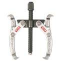 moving the spindle gears required a gear puller, levering onto the casing with a screwdriver might get the first one off but will bend the casing. This is a drama because the casing locates the lid and the lid locates the motor and change gears relative to the spindle. I borrowed a puller from a neighbor but might get one like this from SuperCheap Auto (my local getting spot).
The other problem I had with the spindle gears was that they were, including the spacer, too thick. I cleaned up the faces of the gears with emery paper and sanded the spacer down a couple of mm. Also put a block of wood under the quill and tapped down on the gears using a piece of plastic conduit over the spindle. It’s still not quite enough, the circlip on the top of the spindle is engaged properly but pulled down a little at the middle, you may be able to see this in the photo.
This may be, in part, why the spindle and change gears are not all perfectly aligned top to bottom. I would worried about this except for the fact that the original plastic gears were also not perfectly aligned (worse I think, you can see it in the wear to the gear on its edge in the photo). Also, I am not worried about the metal ones wearing. One day I might have another look at this. Most likely it will involve milling a recess into the bottom of the bottom spindle gear. I will need to have a good look at whether it is already low enough though (maybe its time to get a borescope, not an endoscope they are for scoping one’s ‘end’ for medical reasons) and, if so, a couple more millimeters off the spacer should do it.
I also found that I am not the only one to have identified this problem. This link to the Home Model Engine Machinist forums even shows the problem with a diagram!
UPDATE: I used a friend’s lathe to turn down the spacer between the gears on the spindle to 12mm in height (or heighth for a disturbingly large number of North American machinists on YouTube). I then placed a spacer of approximately 1.3mm under the circlip and on top of the top gear on the spindle (I made it from a mudguard/fender washer using a step drill). This reduced the overall stack height by a couple of mm which means that the circlip now goes on properly and the gears align properly.
I used some nice grease with a little molybdenum disulfide in it to coat the gears, they are quite well made but not polished.
The mill works again, the tolerances are, like I say, not perfect but it seems fine. Hopefully I won’t crash it again. I was using a fly cutter (with a morse taper, not in a collet) and a tungsten carbide tipped cutter on steel. It actually worked quite well but wrecked it in the end. It may even be that the previous owner of the mill had compromised the gears before I got to them. There were signs he did not know what he was doing but there were also signs the mill was basically unused too. Whatever the reason, I won’t try it again.
As always, not a how to guide just showing what I did 🙂
