I have recently, with a friend, wanted to test the charge and discharge characteristics of lithium cells at very high currents. Up to 30 amps for ex-Tesla 21700s. I built a spring loaded tester to do this. I do love making experimental apparatus.
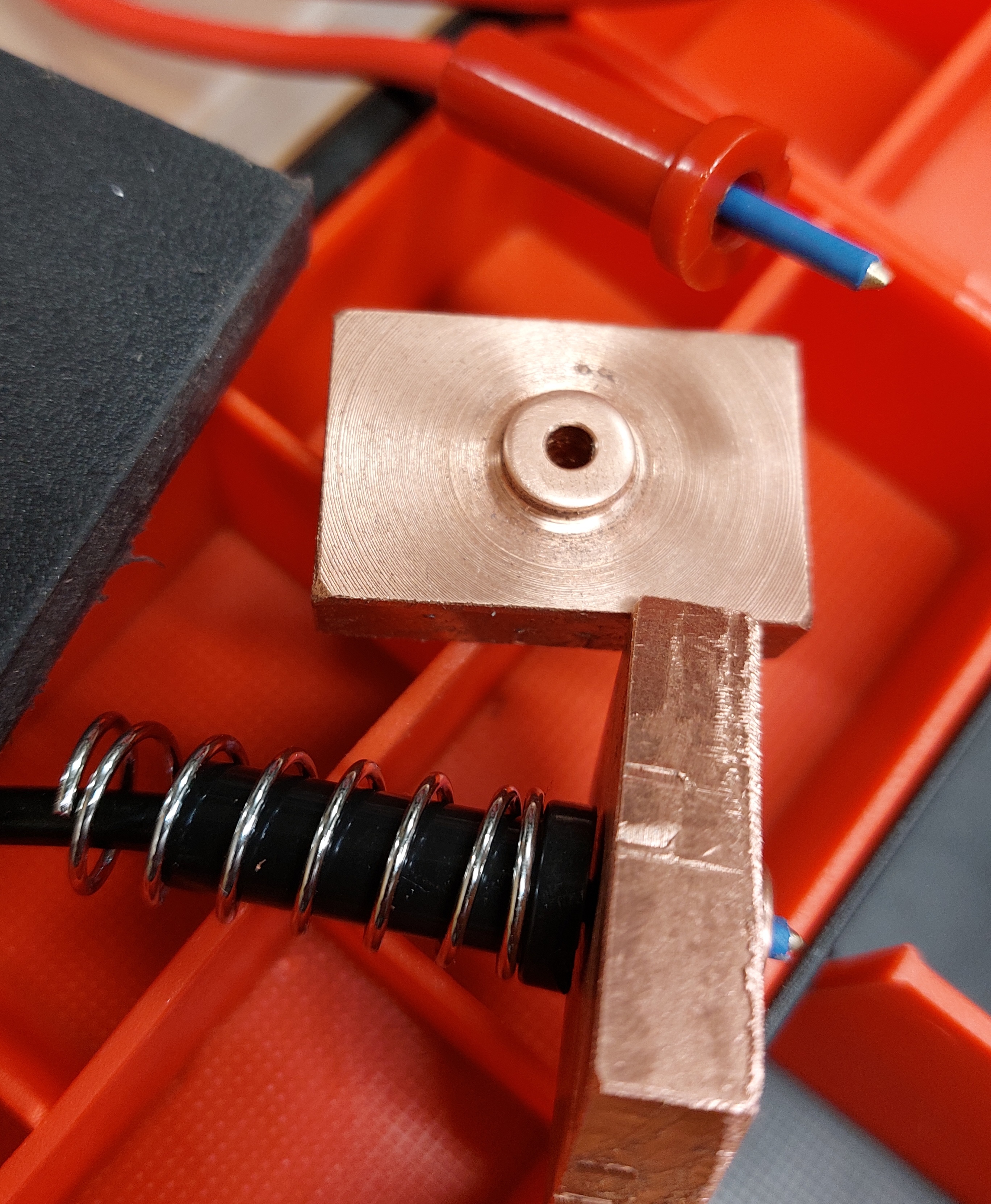
I DO NOT recommend you do this. Testing like this is extreme and can result in dangerous lithium fires, off gassing, burns etc. Again a blog of what I have done, not what you should do. The cell with damaged wrap is just for the photo and should not be used even this purpose. Oh, and there is some insulation missing on the copper contacts in this photo too. At one end of the cell, due to the whole ‘can’ being live, both positive and negative appear together separated by very little. The copper pad needs to be better protected against causing a short circuit. The shiny aluminium tube on the red centre wire could use some heatshrink too etc.

The design of the tester is interesting in a few ways. First I made it from acrylic I bought as scrap from a local plastic supplier years ago. It is cool the way it shows the internal springs on the sense wires (more to come on that). To make it so transparent I fine sanded the acrylic and then waved a gas torch over the surface. I think it is called flame polishing. It is a stinky toxic process (again with the ‘this is not a how-to guide’ stuff) but I only did it to the tops of both end blocks.
The black plastic is an old chopping board, something with a higher melting temp would have been better. However it turns out that the moving copper pad (jaw?) does not get very hot compared to the other end due, I am pretty sure, to the design of the cell casing described above.
The brass rods (what I had) slide in and out of reamed holes on a bit of furniture wax. I need a variety of spring strengths for different purposes and they are easy to change on and off the rods too. RC car shock absorber springs were better than the heavy ones for the larger 21700 cells. Getting everything aligned was mostly done by stacking parts and drilling through on a accurately set up drill press. I have a milling machine but it was otherwise occupied and lacks a digital readout anyway.
So, sense wires. Each end is a Kelvin contact (as in the temperature scale that bears Lord Kelvin‘s name among other things) because it has two separate wires to the cell under test at each end (four wires total). Not the two heavy cables at each end (1.28mm^2 each), they work as one. The ‘two wires’ are the heavy cabling first and the finer central spring loaded wire second. With the two wires being separate, the huge currents that pass through the copper blocks, having come in on the fat wires, do not interact with the smaller sense leads.
This means the sense wires allow the voltage to be measured right at the cell on dedicated wires. The voltage drop that will appear on the far ends of the current wires will be massively higher than the voltage drop across the cell under test. This is due to resistance in the supply wires, the connection into the test device and contact resistance from the copper to the cell.
This picture show the display on the test equipment.

For the purposes of understanding the performance of the cell holder this device is reading voltage and current from the cell holder through an XT60 connector (amazing connectors). The voltage on the load wires is 2.299v. The actual voltage at the cell from the sense wires is 2.533 this means that resistance from the cell to the sensor in the test equipment is 0.234 at 24.06 amps(!!). This means the cell holder’s resistance, including an XT60 connector, is just under 10 milliohms. despite careful design, I did not expect such a good result. The tester right though to inside the test instrument is responsible for dissipating less than six watts.
Here are some parts fresh of the lathe.
The copper is off the lathe anyway, the probes are from an old school multi-meter, so old school it does not even use banana plugs there are the ends that plugged into the meter. Copper is the ideal material for electrical conductive. It is second in conductivity only to silver and (subject to surface oxidation) better than gold. As a metal for turning on the lathe it is a bit of a nightmare. It is so malleable that it wants to smear instead of cut. Sharp tungsten carbide tooling (designed for aluminum mostly but broadly ‘non-ferrous’) helped.
