I recently installed an XT bridge board in my Amiga 2000, the A2088XT. I wanted a hard-file for it that was all set up. I am rusty with MS-DOS and I am not motivated to reacquaint myself with it, I have Amiga DOS 🙂
I have wanted a bridgeboard ever since I sold my A1000 sidecar. Here is rough video of me starting the sidecar, you can hear how excited I am. I also have a video on Youtube of the setup described here.
Hard-files, the cheapest virtual HDD
A hardfile is a, usually large, file that behaves for some software or another on the system as if it were a separate hard disk drive. Access is therefore through the host system which has speed implications for the software with the pretend hard drive. They are easy though and work well.
The bridgeboard hard-file format is compatible with the PC-Task format. I actually tested this early in my experiments in getting a hard-file working. I never planned to run a 5.25 inch floppy drive and figured that was OK, the PC Task users don’t either. I do believe I can plug an Amiga floppy into the back of the bridgeboard though.
My concerns began when I realised that a downloadable hard-file for PC Task / Bridgeboard users was not a thing (nor for the incompatible PCX). I did find one, and it worked . It is from the AIBB FTP server. It is just MS-DOS though. It did not like the XT and, once the boot floppy drive fails on startup (I don’t have a drive at all), and after pressing F1 to continue, holding down <Shift> skipped autoexec.bat to leave me with a C prompt. Win.
Making an Amiga PC hard-file from a generic .img
But what about some games? Over on the internet archive I found some cool MS-DOS hard drive images.
I downloaded tdl hdd.img It contains hundreds of megabytes of games organised by year along with terminal software, Total DOS Loader to index and launch games, and other tools. It is a hard drive image designed for a MiSTer. I may buy a MiSTer one day.
This image is not a bridgeboard / PC Task compatible file. However, late last year user “MOS6510” published python code on github to convert raw images to Amiga PC hardfile images. What a legend.
I had never run python before. I downloaded it from the MS Store, opened a command prompt at the location of tdlhdd.img (which I had renamed to remove the space for convenience). Next I typed python and, at the python prompt, followed the github instructions. A new image file was rapidly produced.
Adding a hard-file to a bridgeboard
Once the image was over on the Amiga there was work to do. I had already installed the Janus Tools DOSServ hard drive handling files update from Aminet using the included readme instructions. I am not sure if it is necessary but given the original Janus tools floppy installer only allows for up to 32megabyte hard drives I think it probably is. One future project would be, using the extra DOSServe features, to copy the contents of the hard-file into a HDD partition for better speed too.
I then edited (ed) DH0:PC/System/aboot.ctrl to refer to the new hard drive file. Some notes:
‘DH0:PC’ is just where I chose to install the Janus software to from floppy
I could not simply replace the original hard-file, created on DH0: during installation of the Janus software, my Workbench partition is not big enough
I had renamed the hard-file to TDL with no extension, the original hard-file created by the Janus setup floppy had no extension (.xxx I mean)
Following the guide in the Janus Tools package, the aboot.ctrl file has no carriage return
Nothing happened when I reset the XT so I power cycled the Amiga to get Janus to look for a new aboot.ctrl. It booted the Hardfile!
We are in MS-DOS now!
A lack of memory (or memory management ability) caused a minor error (press f for fail after resizing the window a bit) and the computer loaded into Norton commander.
I navigated to c:\Games\1981 and pressed enter to start TDL.exe, chose Eliza 3.0 and started the game using the .bat file that was automatically unpacked to a temporary folder by Total DOS Loader.
Done. Plus, if you review the Eliza screenshot there is a peek into my psyche.
Probably need to buy a ram expansion. Also, no double entendre was intended in the drafting of this post.
I have a few different kinds of original Amiga computers. They are mostly built up out of hardware from the olden days too. I do love them. They are shining artifacts of the past. They are museum pieces. They are rare and esoteric. They have a certain look, smell and sound. They are fascinating in all sorts of ways.
They also misbehave, require maintenance and have crazy quirks. They have highly nonstandard video outputs. They are EXPENSIVE to procure, expand and maintain.
Emulation
Emulation of the Amiga thanks to the Universal Amiga Emulator, normally known as UAE, is phenomenally good.
The usual choice for windows is WinUAE. For Linux and Apple there is FS-UAE. UAE is available for free. It is great software that runs fast enough to beat Commodore’s fasted Amiga by 50x or more on even modest modern computers. Expensive real word cards and expansions can be added to emulation just by checking a tick box.
I run FS-UAE on Lubuntu on a used $50 thin client from ebay. But any laptop or desktop or even a Raspberry Pi will do. In fact the pistorm amiga accelerators are a Raspberry Pi amiga emulator running on an amiga 🙂
A real joystick is a good idea though, a USB Speedlink Competiton Pro (which also comes with emulated games by download for an instant experience) is less than 50USD. I think I got mine from Amazon and it is great.
To get UAE running fully some proprietary ROMs are required, which is a pain but they can be found very cheaply. Then, armed with some Workbench 3.1 floppy disk images in the .ADF format (which seem to be freely available) and a pre-configured Classic Workbench environment, a full Amiga desktop environment can be setup very quickly.
Barely recognizable to someone familiar with a basic Workbench 1.3 or 2.04 or 3.1 install but so slick to use. Of course a standard workbench installation can be performed on a virtual hard drive too. Swap those virtual floppy disks like it is the virtual 90s.
Another option is to buy fully configured Amiga emulation (which has UAE behind the scenes) sold as Amiga Forever. The plus edition is pretty feature packed and prefilled with games and demos and costs 30USD. Less than a console game. It was where I started with emulation in 2014 and it required no particular knowledge.
Amiga forever can also be the source of copyright software for installing the slick and impressive AmiKit. Amikit is a highly configured Amiga desktop environment that is ready to go. It can launch PC application inside the Amiga desktop and could be a person’s daily driver operating system.
Games
Games for the Amiga are available on .adf floppy disks. These can be inserted into the emulator and booted just like that. I insert them as read only mostly because they can have viruses on them from the old days. Mostly not though. I still sometimes do this on emulators and on real computers for the demos that often come prior to the game loading. Mostly I use WHDLoad both on real Amigas and under emulation.
With a virtual hard drive and WHDLoad software, games can be launched from the Amiga Workbench desktop. Exit back to Workbench is also possible. But who ever wants to leave the Shufflepuck Cafe?
WHDLoad game packages and ADFs are available from all sorts of places. Google is your friend and mine. They are usually copied to a virtual hard drive by adding a host system folder as an Amiga hardrive in the emulation (neat!). If you know me in person ask me if I can help if you like.
Downsides?
There are very few downsides to emulation. One is that it is hard, or impossible, to get perfectly smooth scrolling all of the time. It is not like scrolling is jittery but with so much Amiga software hard locked to 50 frames per second and so few monitors able to go below 60 there will be minor discontinuities. I suspect there are ways to overcome it but I have never bothered.
Emulation is great. There are some who say it is ‘not real’ or whatever. Meh. Fire up an emulator, load a favourite game and have fun. As your world contracts to a rectangular space established nearly 40 years ago the fact that it is due to genius emulation software should be a source of delight.
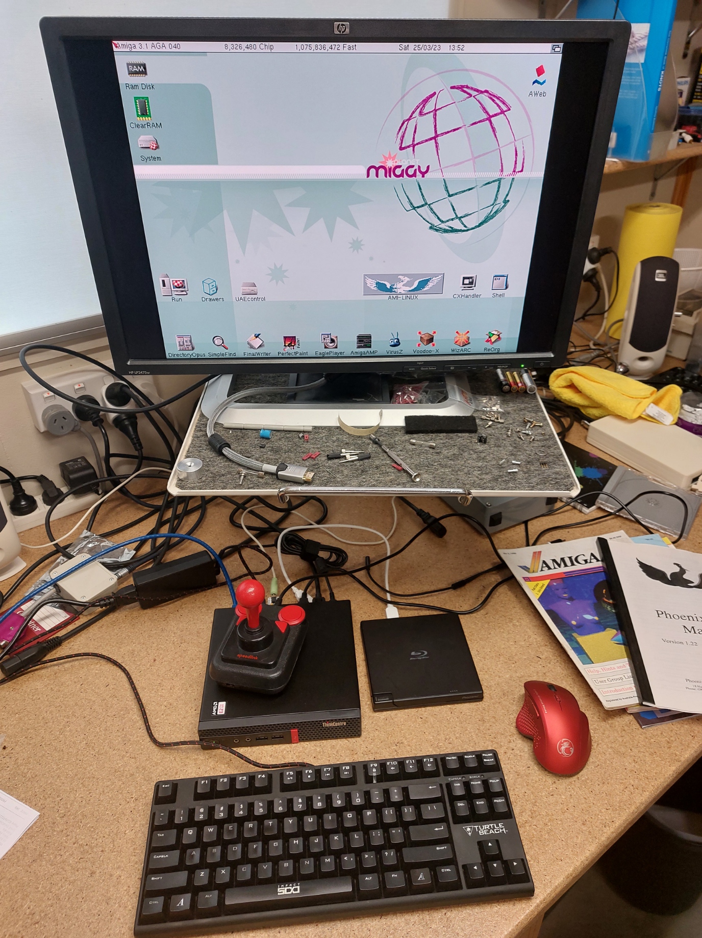
Update April 23 2023: Picture of the display setup at the 2022 Canberra Vintage Computer Exhibition:
The Amiga 1000
The Commodore Amiga 1000, the first Amiga, launched on 23 July 1985. The launch spectacle showed off the new computer, and its state of the art technology, with live art by Andy Warhol amongst other things. The A1000 launch is on YouTube. The computer is a beautiful piece of industrial design and, at launch, was the best home computer available.
In early 1987 the Amiga 2000 was released. It was full of internal expansion ports and, soon after, new technologies for managing memory allocation (AGNUS chip) and a few extra screen modes that the A1000 could not support.
In around 1991 an Australia business, Phoenix Microtechnologies Pty Ltd released the Phoenix replacement motherboard for the Amiga 1000. It supported the latest memory allocation technology (Amiga 3000 level) and had an A2000 expansion slot and an A2000 video card slot. It also had an onboard SCSI hard disk drive controller and maths co-processor if optioned. This is the motherboard pictured here.
The excellent web database of Amiga computer hardware ‘Big Book of Amiga Hardware’ contains a page on the Phoenix A1000 motherboard. It notes that the board’s creation was subscription funded. I cannot find a reference but there has been some talk that this is the first recorded crowd source funded IT project. Different information (though with much overlap) can be found on the also excellent Amiga Hardware Database. Amiga users are well served with hardware information.
This is an original board from the 90s (a few new-old-stock ones were released in the mid 2000s). The board is a beautiful thing including ICs with gold lids in ceramic packages (brown paper packages tied up in string etc.) It is covered in text, top and bottom. On the top these include creator Andrew J Wilson’s signature in the copper and the poem Desiderata in the silk screen. On the bottom the details include an apology ‘Sorry Sheldon we did it anyway’, thanks to 540 subscribers and a shout-out to the first subscriber and to ‘The Wizards of Amiga for a magic machine and O.S.’ Boxes for quality checks are near the front edge and are hand numbered and initialed.
I found an article in an old magazine of mine, the Australian Amiga Annual 1990. It is from the from the early days of the project and details the subscription / deposit funding model:
Having acquired a bare board many years ago I decided to make a working display case for it. Here is how it looks:
The picture shows a fast RAM expansion, SCSI2SD, floppy drive boot select switch, Kickstart switch with Kickstarts 1.3 and 3.1, drive light, hard disk auto configure enable switch. There are also connectors for an HDMI port (from a RGBtoHDMI yet to be installed in the video slot in this photo), a custom external PSU, and A2000 keyboard. The bumper stickers are to allow the machine to work upside down or on its side without anything getting scratched.
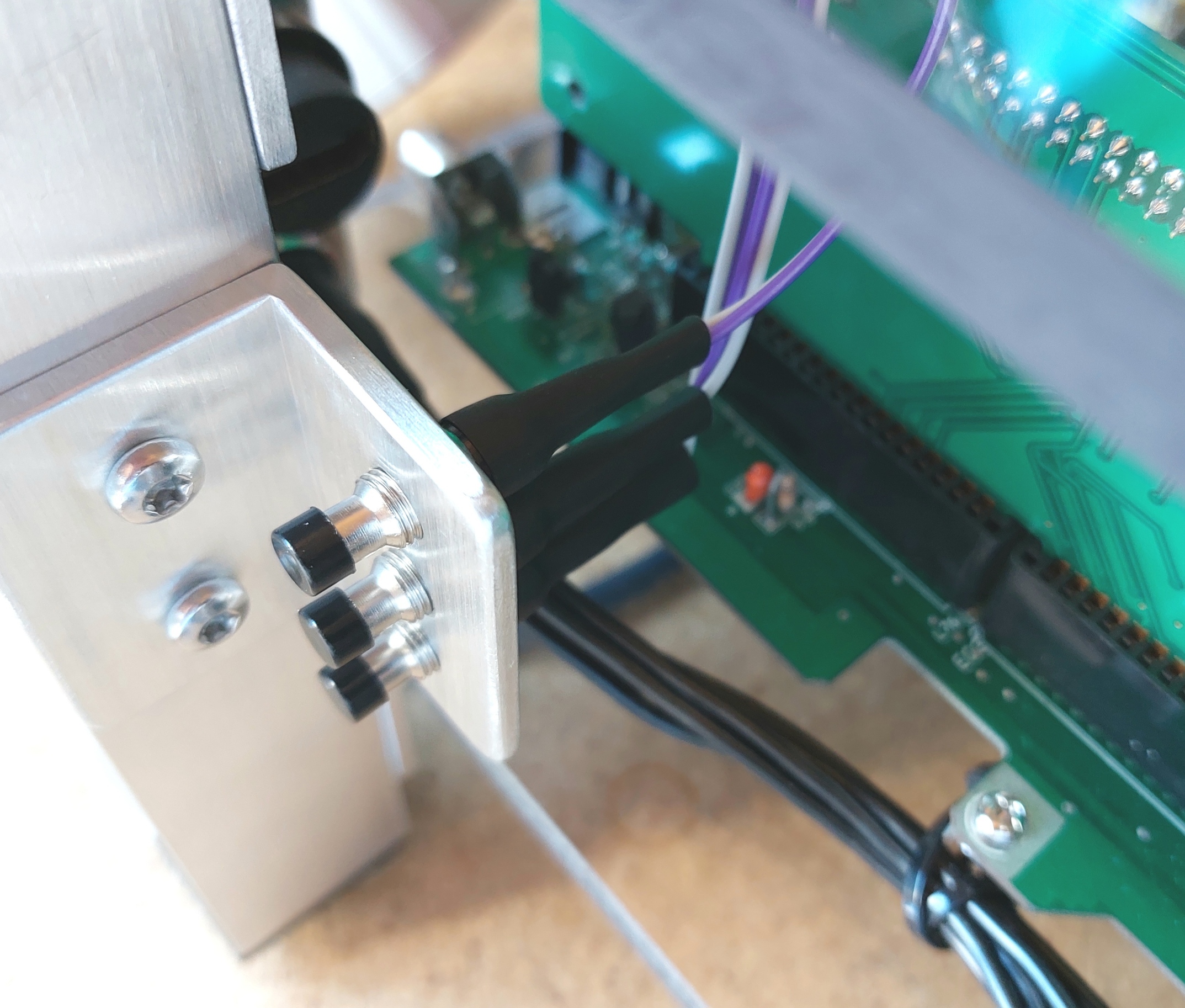
Here are some detail photos showing:
power LED and HDD auto configure switch at the front
joystick port strain relief at the front
HDMI out and power in at the back
keyboard adapter and drive/ Kickstart switches at the back.
The external power supply with its 3D printed badge looks great. Since the photograph was taken a thermostatically controlled 60mm fan has been added. While it is designed to be ultra safe there are no photos of the internals, this blog, as always, is not a ‘how to’ guide. There is certainly no ‘how to’ for DIY mains wiring anyway. That work is for licensed professionals.
The computer works well and has been running Workbench 1.3 and 3.1 for days now. WHDLoad is supported and all Amiga Test Kit tests pass. It is an excellent Amiga.
April update: Thanks to intric8 at Amiga Love, I now have a really nice phoenix sticker on the case:
I was very pleased to add this, I did not have the logo anywhere on the computer until this arrived from the other side of the planet.
Build details: Electronics and switches
Power LED: The two colour power LED was, to my surprise, incredibly tricky. I wanted to implement the colours specified in the manual. This involves an orange ‘on’ colour turning to green during HDD activity, red is used to denote a system malfunction of some kind. I purchased a large (10mm 3/8″) two colour LED, it has three legs. The middle leg is common or negative and the remaining two legs power red or green. So, when the computer is simply on both red and green LEDs are on making orange. When the hard drive is active the red LED turns off.
The manual gives no explanation of exactly how the factory power LED is wired up (it replaced the Commodore LED). It does mention a ‘hidden resistor.’ LEDs connected to power need a resistor in series to keep them from burning out and one at least was, apparently, needed in the cabling. Various attempts, including a resistor on common and two resistors, one on each colour, failed to work properly.
It became clear that the green LED needed a resistor (on the green positive lead at 100ohms for my LED) but the red LED needed a direct connection to the motherboard. Something about the switching circuit, perhaps just an onboard resistor to guarantee low current switching, meant that any further resistance on red stopped it from working. So the ‘hidden resistor’ is for the green LED only.
The manual is also not perfectly clear on which KED pin is what. I have connected LED2 REAR to red, LED1 RIGHT to green (through a 100ohm resistor) and LED1 LEFT to the LED’s negative lead. The RIGHT, LEFT, REAR, FRONT nomenclature is from the phoenix manual. Looking at the board from above so that the ports are at the REAR the other directions were correct.
Kickstart Switch: Like the power LED I think this was supposed to be purchased from Phoenix Microtechnologies. The manual provides excellent information on how to jumper the Kickstart selection link block. The factory switch has three leads.
I have two genuine ROMs (not EPROMS) as U53-ROM1 (KS3.1) and U54-ROM2 (KS 1.3). The manual is clear that I need to leave the FRONT two pins of L42 open and switch the rear two. This is what I did and it works well. The third wire on the factory switch should go from L42 REAR RIGHT to L35 middle. This will prevent the HDD from trying to auto boot off the second ROM. This makes sense in most original cases because the Workbench install will only match one ROM. Interestingly this is not a proper implementation of L35 it should be either centre and LEFT or (XOR) centre and RIGHT.
Please note, I have not actually built one of these. This is a blog about what I have done, not advice on what you should do without having a good hard look at this for yourself 🙂
Hard Drive Auto Configure Switch: I have wired a switch up (next to the power light) to separately operate L35 rather than use the factory layout tied to a Kickstart switch. This lets me switch hard drives (MicroSD cards) and boot different installations under different Kickstarts. It’s also the only way to see the glorious insert workbench icons splash screens 🙂
The switch is also necessary with my setup to allow booting from floppy with an un-configured hard disk drive (blank MicroSD card in my SCSItoSD). For some reason the computer gets hung up on the un-partitioned card. It would then not see partitioned but un-formatted space after booting with a floppy until the switch was back in the auto configure position. The less said about how long it took to figure this out the better.
Contrary to my reading of the manual I needed to leave L14 open.
Floppy Drive Swap Switch: The floppy swap switch allows an external drive to function as DF0: for booting. I need this because, to keep the board clear for display, I have not attached a ribbon cable to the floppy header. Floppy numbering (allowing a user to hack into the CIA lines out to the floppy connectors) is done at L8. Four jumpers each running FRONT to REAR (or REAR to FRONT, same same) is the default setting (check the manual for yourself!) but if the leftmost two are cross connected in an X DF0: is on the outside and DF1 can be on the inside. The manual contains further details.
I had to draw a diagram to figure out the switch (though you will see a white dupont connector cable loop in the first picture of the board in this post that sufficed before I made the switch.) Figuring out an order of operations to get the heatshrink perfect was also tricky.
The switch drawing above is rough but effective. The two boxes drawn over the switch contacts (top) give a guide about what is grouped together in each of the two switch states. With hindsight, a centre off switch might be a useful way to disarm all drives (I think that is what it would do), especially with an external gotek/flashfloppy emulator which usually has a disk ‘inserted’ at all times.
Power supply: The supply is connected/strain relieved with a 7 pin GX20 aviation plug, power then goes to the motherboard connector. The Phoenix board has a jumper like the A2000 so that a tick is not strictly necessary (L125 RIGHT to obtain tick onboard). However, a crystal locked tick PCB is readily available and is incredibly precise. I have a spare PCB if you need one.
I checked the motherboard connector pinout against a real A1000 PSU about five times after being sure I built it right in the first place. Once check involved drawing the 7 pin motherboard connector twice, I then filled in the voltages for one supply and hid that drawing, I then did the same for the other supply and compared the two drawings.
RGB2HDMI: The Amiga’s video out is a dated standard. It is an analogue video connector on a DB23 plug. It does work well and there are plenty of options for converting these signals into whatever format is required.
Fairly recently though work was done to intercept the digital signals and use a Raspberry Pi Zero to convert them directly to HDMI. For computers without internal slots, like the Amiga 500 or the original Amiga 1000, the RGB2HDMI is plugged in under a chip (as are things like the Indivision converters which work OK). Starting with the Amiga 2000, a video slot with all the digital signals exposed became available. The Phoenix board also has such a slot, here is picture showing the RGB2HDMI card, the button bracket and, blurry in black at the back, the HDMI socket that will provide full strain relief when I can finally purchase a Pi Zero. Once I know the card works I will move the button connectors to the side of the card closest to the switches (I would not attempt to do a warranty return on a card I had soldered on).
Helpfully pin 1 on the slot is marked by a diagonal in the corner of its box on the silkscreen of the PCB and pin two is clearly marked on the RGB2HDMI. I also have not come across any information that the video slot is back to front and the RGB2HDMI has an arrow on it that has to point to the back of the computer. I have some recollection that the Phoenix board’s Zorro slot is back to front (it is on the ‘wrong’ side of the CPU compared to the A500 and A2000) but I am not sure, investigations are required.
The button bracket is drilled and tapped for the buttons. These switches, like many similar items including some rotary encoders I have, use an odd thread: “M7 fine”. It is a metric 7mm thread and with closely spaced threads of 0.75mm pitch (the distance between thread peaks). Most metric thread charts have no M7 thread at all and M6 normally has a 1.0mm pitch. I bought a tap especially. The drill size is odd too at 6.25mm (thread size – thread pitch for metric). Thankfully 6.2mm drills are fairly easy to find and in soft materials have been close enough.
Clock Battery: A standard CR2032 clock battery holder fitted well with only an extremely minor zigzag in one of its pins. I took care to run the zigzag close to the holder and to not mess up the clip mechanism which assumed the pins will be pushed fully down through the PCB. It just cleared the poetry to the LEFT of the battery position. I considered using a smaller CR1220, my A1200 clock uses one, but given the amount of time these computers are left disconnected from the mains and running on the backup battery I concluded that the larger cell was a good idea.
I do need to check whether the board is trying to charge this cell. A rechargeable cell in the 2032 form factor may be required.
The second photo shows that the hole in the motherboard is barely impinged upon too. If it mattered I would whittle down the plastic of the cell holder ever so slightly for perfect clearance.
Capacitors: As far as I can tell all the yellow capacitors on the board are plastic film capacitors. They have no electrolyte in them to leak and, subject to high voltage transients (unlikely) should last (for practical purposes) forever. Of the five electrolytics two are near the audio ports, I left them alone. The three near the power connector see significant ripple currents and were discoloured on top and there were rings that looked liked dried liquid on the PCB underneath the 12v and 5v capacitors them when I removed them. They were made by Daewoo. I took a picture of the board with the capacitors removed, an old capacitor is in the picture leaning on the power connector:
I replaced them with the best parts I could buy. Long life, 125C low ESR Vishay capacitors. Like the originals they are 470uF 16V capacitors. They are 1.5x the height (height-th if using inches) of the originals but the same diameter. The -5v capacitor had not leaked (it does not see much ripple current). This is partly why I do not suspect trouble with the audio capacitors (I also have a proper LCR meter which suggested the removed capacitors were still pretty OK for capacitance and ESR). On the topic of the -5v capacitor (which is in a sense back to front) the silk screen was right on my board. I always photograph capacitors prior to removal for checking against the silkscreen when the paranoia arrives at soldering time (cidering time if soldering in inches).
New capacitors installed. Next to AGNUS, behind the leftmost capacitor, the hole in the motherboard is plugged with black plastic. This is a part I turned to be a gentle push fit into the board. It goes in from the bottom and stops on a 1mm shoulder. Underneath there is a 15mm long cylinder (same length as the PCB standoffs) to support the board in the middle.
Materials: DPDT switches, wires and headers from long since discarded PC case plus some extra dupont headers. 5 pin IEC socket (keyboard) 4P4C plug (keyboard, these are quite skinny, they have 4 positions and all four are connected, phone plugs usually have 8 positions of which only four are used/connected), 7 pin GX20 aviation plug (power), HDMI pass-through plug, 10mm Red/Green LED and 100 ohm resistor.
Build details: Aluminium and clear polycarbonate
The top and bottom are 8mm thick sheets of machine guard poly-carbonate from Bunnings (I think in the US it would be Home Depot). Machine guard plastics should be static dissipative (to prevent dust from machines being attracted to them.) It appears to be. It is stronger and harder than acrylic and provides a good basal platen for the motherboard, in my design it is structural too and while there is a little wobble without the top on, it is rock solid once it is screwed on.
The motherboard mounting holes were tricky. They had to be close to spot on. I had originally planned to tap the poly-carbonate but there would have been no tolerance other than the diameter of the holes in the board. By using screws and threaded standoffs I could drill the holes in the poly-carbonate 0.5mm over-size too. Initial positioning of the board was done with three holes, in each hole I had a pin (turned to size on my lathe) that exactly matched the motherboard holes and the hole in the poly-carbonate. This super accurate positioning (the board could hardly move at all and its holes were perfectly concentric with my first three holes) meant I could then take a drill, close to the size of the motherboard holes, and spin it by hand to mark the locations in the plastic. The final 15mm standoff height was chosen to enable the ram expansion to fit on the side expansion connector.
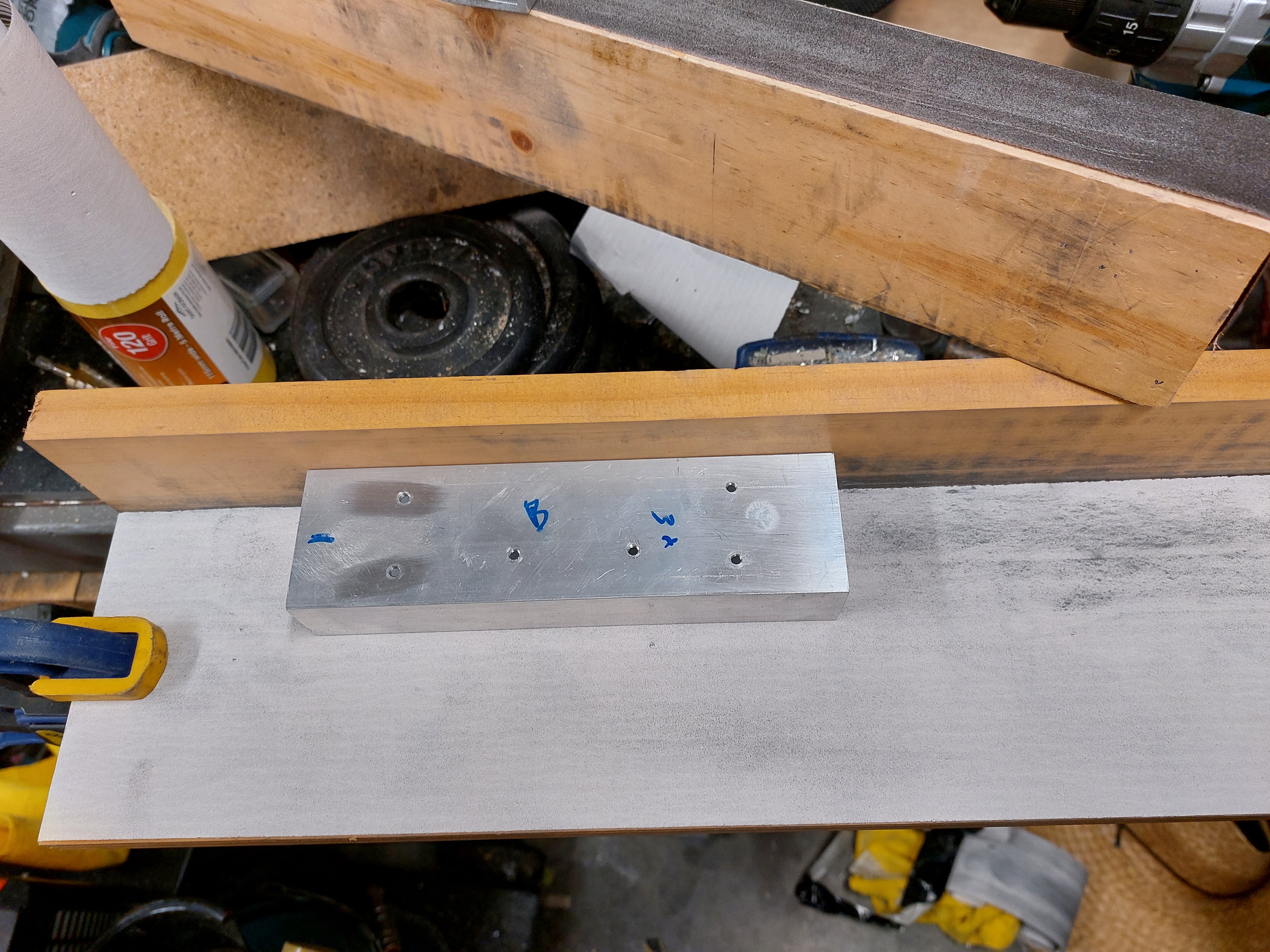
I was not sure how to get a nice brushed aluminium look. The parts all needed tidying up, thankfully someone on YouTube had a clue and I used their method. The picture below shows one of the legs. It is marked to show where it goes (the parts are interchangeable but do work best where they were made. The dot on the right hand side is superglue from assembly prior to drilling and tapping the leg.
There is not a lot to say about the aluminium. The parts are stamped to show which one goes where but they are close to perfectly interchangeable. It is laborious but the method to attach a piece of angle to a rectangular leg was:
Drill holes in angle to tap drill size
Clamp or superglue (you can see some glue in the picture above) the angle into place. Spacer blocks are always more accurate than measurement for this purpose.
Drill through the tap hole in the angle into the leg.
Tap the leg
Drill a clearance hole in the angle. This can be slightly oversize if some tolerance is required.
Materials: Aluminium section and end plugs, aluminium angle, lots of stainless screws and washers, 15mm PCB standoffs, 8mm poly-carbonate machine guard plastic (should be static dissipative).
Build details: Jumpers, SCSItoSD, pbscsi.device and Worbench Installs
Jumpers, jumper blocks, links: The Phoenix manual talks about links, not jumper pins or jumper blocks. In any case things can be configured by joining up a bunch sticky outy bits of conductive metal on the board. Most older motherboards have at least some jumper pins on them. The Phoenix board is a porcupine.
I have mentioned jumpers a few times in this blog post. The two reference documents I turned to for the Phoenix board were the original manual (the drawing showing locations of jumpers was a life saver, I printed and laminated it) and a PDF that is useful to clear things up available from Retrohax article. I note again that with my current setup I need to leave L14 open despite the manual’s default settings recommendation.
I use jumpers with tabs on the top for easy removal and installation, they also show where I have been fiddling because default ones are usually standard stubby ones. Recommended.
A final observation on jumpers on a board of this age. If the expected result is not achieved it could be a worn out jumper. My board was set to use an onboard source for tick when I got it. A factory power supply had worked days before, mine without tick did not. I pulled off the jumper, was pleased to note a loose fit on the suspect part, and put on one of my own. Problem solved.
SCSItoSD: Instead of a precision spinnage of magnetic media that is a vintage hard disk drive, the SCSI controller/interface on the Phoenix board is connected to a hard disk drive emulator, the SCSItoSD v5. There are newer and better emulators including the Zulu SCSI which is top shelf stuff. I bought this one years ago though, when the future of vintage computing was unclear and I did wonder if it was my only chance to get a drive emulator. I am glad to have it in use.
The drive emulator is configurable over USB using a small executable file under Windows. Mine is set to defaults (largely), to emulate two 2gigabyte SCSI2 hard drives at Device 0 and Device 1. One gigabyte would probably have been better, given where I ended up, but it is set up now and working well (EDIT: but temptation got me and I created another train wreck, now emulating 952 megabytes, 900 more than I had in the 90s). With my MAST ram expansion, earlier versions of which are said to interfere with hard drive autobooting in the Phoenix manual, I had to set a 2 second delay into the drive emulator (one second was slightly marginal). If it was set to be ready as soon as it could be the computer would only autoboot after a soft (keyboard) reset when first turned on.
It was not clear what would happen if I removed the microSD card from the drive emulator, connected it to a Windows computer and mounted the card as a hard drive in the WinUAE Amiga emulator. To my delight it immediately booted my Phoenix install on Device0 and allowed me to copy files to both of the partitions on it. Device1 did not auto-configure (fair enough) and I have not yet tried to access it under WinUAE.
I deleted a chunk of stuff here on 26 April 2023. I had hard drive problems using default settings (the ROM vJ with no polled SCSI software update at boot, and link 30 open). I found I could reliably bring the problem on by ‘leaving out’ and then ‘putting away’ the DOpus icon.
At 25cm my SCSI cable was not a particularly long cable. However, with thanks to information from the friendly people on the A1K forums, I was moved to shorten it to 8cm. The problems is not completely fixed but is much better. If I load the polled SCSI driver it works fine, just a bit slower. I may be able to clean up the remaining problems with SCSI2SD settings.
I am just going to run this with the Phoenix HDD defaults. Using the sysinfo HDD speed test the default settings give me 112500 bytes/second where under polled SCSI with or without L30 closed I was in the 60000 range. I won’t be installing a CD ROM so polled SCSI does not matter much. I won’t be doing the hardware mode either, it sounds great but I am trying to leave this one original.
pbSCSI.device: The Amiga’s operating system is beautiful. It is parsimonious and highly configurable. It is reason enough to spend time on one of these early computers, just to see how clever an OS can be. Transitioning from AmigaDOS to Windows 3.1.1 was grim (however necessary it was at the time). It was not until Windows 2000 that I felt I was back on a winner and I embraced it with enthusiasm, but still missed my AmigaDOS shell.
pbSCSI.device is the device file for the Phoenix board SCSI controller. It goes in the devices (DEVS) draw, it is a tool type for the hard disk configuration tool icon (or argument at the command line) and it is on the ROM on the Phoenix board. For ease of use I keep pbSCSI.device in DEVS on my installs but don’t use it much after first setup is done. I have amended reference to SCSI.device in HDTooBox’s tool types to refer to pbSCSI.device (I just right clicked on the icon and typed in the “pb”.)
The picture shows the mouse pointer hovering over the icons/information menu. When the HDToolBox is the selected icon, clicking here brings up the window for the icon shown. The line in the Tool Types: SCSI_DEVICE_NAME=pbSCSI.device did not previously say ‘pb’ before ‘SCSI’. I had previously copied pbscsi.device from the phoenix floppy to my Install3.1 floppy disk’s DEVS drawer. I found I also needed to copy FastFileSystem from the install floppy to L: on WB3.1.
The FFS on the 1.3 install, I believe, is a specific version that goes with it (it is about half the size and I am left wondering if the 3.1 version contains two versions in one file). One day I will try replacing it with the 3.1 version to see what happens.
When I am feeling brave I am going to start using Polled pbSCSI.device for a bit of a speed increase. Such a flexible OS. I will not be amending the board for a pseudo DMA configuration.
Install Workbench 3.1 to Hard Drive: With the board powered up, connected to a display, keyboard, mouse and floppy drive emulator as device DF0: it was time to install Workbench. This is how I install Workbench 3.1, it should be the same for 1.3:
Turn off hard drive auto configure at link 35 (to allow floppy boot with unconfigured SD card in my drive emulator).
Boot from install3.1 with pbscsi.device in the tool type for the HDToolbox icon after putting pbscsi.device into DEVS. I do all partitioning and formatting from there. This is the only way I can know that all drives have the 3.1 version of Fast File System.
Delete any old drive types and autodetect the SCSItoSD drive (HDToolBox).
Partition the drive. A few hundred megabytes for Workbench is enormous. I am not sure exactly where the limits are, but I am emulating a 952 megabyte drive. While I was still learning, the HDToolBox on the Phoenix floppy at least did not work at all with more than 2gig and seemed less than perfectly reliable over 1gig. More experimentation would help (HDToolBox).
Save changes to drive and low level format and save changes to drive again for good measure (HDToolBox).
Turn on hard drive auto configure at link 35. Boot the Workbench Install floppy again. Turning auto configure on makes the hard drive partitions pop up (as I should have always expected but these things are a variable (sic) soup).
Format the drives using Workbench’s format menu. I have international and cache turned off. I have not tested with it turned on. Then double click on install Workbench.
Here is an install (one of many along the way):
I grabbed disk.info from the phoenix floppy and put it on DH0: where my Workbench install lives to get the Phoenix icon on it. Not a bad image. My old HP wide gamut monitor has an s-video input and I have an Amiga RGB to s-video adapter from Kipper2k. It is perfect for testing because it is utterly reliable, no wondering what has caused a black screen.
Workbench 1.3.3 Install: It has to be, I think, at the start of device 0. It is essentially the same as a WB3.1 install I think. There is no install file for WB 1.3, just copy over WB1.3 and Extras to the drive. Something like “Copy DF0: to DH0: ALL”. The all argument takes the contents of folders rather than just creating empty folders.
I copied the contexts of the Phoenix disk over first for some vintage goodness. There is some good stuff on that disk including the document viewer c/phoenixview. I also spooled on ARP, the Amiga resource project floppy. It adds a bunch of stuff that Commodore added as standard in later revision of Workbench.
One of my Workbench 1.3 installs I made using install scripts mentioned in the Phoenix manual that were on a floppy I am yet to find online (and may need to upload). It was magical. The floppy says it is from 21 October 1991 during boot. The first thing it does is copy over (I think) the entirety of the Phoenix disk before copying over Workbench. There are some nice things on their that lend authenticity to a Phoenix board build.
Workbench 1.3.3 is stable but it is there for historical purposes and for niche software. By the time Phoenix was a thing Kickstart 2.04 was around and the improvement in user experience (I recall the joy of upgrading my Amiga 2000 at the time) is incredible. Workbench 3 looks very similar to 2 but supports more modern software. The only thing I miss about 2 is the even blue dot workbench background texture, the one in 3 is not as nice. I will try and copy it over.
Auto selection of Workbench install based on Kickstart selected: It would be nice, I thought, to boot the right version of Workbench depending on the Kickstart (1.3 or 3.1) selected at boot. It is possible, but I have learned that with a SCSItoSD at least it cannot be done reliably. Read more under the heading about SCSItoSD.
File systems are important here. It is easy to end up with multiple versions of Fast File System across multiple drives. I believe this was a source of unreliability for me. It also seems reasonable to conclude that booting into 1.3 with one version of FFS and then throwing over to 3.1 which is setup with a different FFS is a bad idea.
My solution was to add the pbscsi.device tooltype on my WB3.1 HDToolBox (as mentioned above) and create FFS partitions for all drives there. I also formatted them all in Workbench 3.1 in FFS (no directory cache, no international mode which I think is what 1.3 requires but not sure).
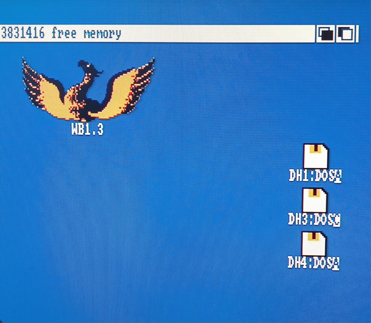
Booting Workbench 1.3 off a partition formatted in 3.1’s (sic) FFS means there are some aberrant additional drive icons on the desktop. I don’t think there is anything to do but hide them under icons for other things. I have also noted that the second SCSI device, while formatted the same, does not produce one of the aberrant icons. Here they are in a photo:
I have grown to be glad to seem them over multiple install iterations. It means I have things right.
So on to the dual boot setup. It has to be so that the computer starts by trying to boot 1.3. A 1.3 ROM cannot ‘see’ a 3.1 partition to kick off the process. This means that in every case the computer will start by heading off into the s/startup-sequence script in the Workbench 1.3.3 install. This guide explains how to automatically detect which Kickstart ROM is operational and to boot the proper Workbench version accordingly.
In summary the original 1.3 startup-sequence gets renamed. A new startup-sequence is created that checks the Kickstart version and uses an if statement to either use the original but renamed startup-sequence or do some preparatory work and run the 3.1 installation’s startup-sequence.
The guide is good (though commentary on FFS versions would have helped me) but it can be improved. I added some echo statements, alongside the assigns specified in the guide to tell the user what is going on:
Echo ” “ Echo “Kickstart newer than 1.3 detected” Echo “BOOTING Workbench 3.1 install on DH1:”
The first echo is for a blank line and, yes, I fixed the ‘Workbenmch’ typo, the version in the photo was an attempt to fix ‘Workbemch’:
The second problem is that I think the 1.3 startup-sequence is still running while Workbench 3.1 is initializing. I think AmigaDOS (and probably every other OS) holds a script open until it finishes. So, until the 3.1 startup-sequence has done ‘loadwb’ and ‘endcli’ the custom startup-sequence on the 1.3 partition is still open. It will not close until after 3.1’s sequence says endcli at which point control returns to the 1.3 startup-sequence and it can do an endcli.
This causes a requester to pop up multiple times complaining that “Intuition is attempting to reset the workbench screen.” I added the DELAY argument to LoadWB at the end of the Workbench 3.1 startup-sequence so “LoadWB DELAY“. This means that the intuition requester is seen only once and cancels itself. I also have to always remember the way to edit documents on an Amiga is Ed not Edit. Typing ‘q’ and enter exits edit when accidentally launched, the escape key, x then enter saves and exits ed.
In the hope of snapping the 1.3 startup sequence shut fast at the end of a 3.1 boot I also changed the code used in the guide script. I think the original code is more ‘by the book’ but my main programing experience is BASIC on a Commodore 64 so don’t stand too close when I am working 😉 I also added a >NIL: to the first line to prevent it reporting the version on screen. Here it is in phoenixview:
Dual or multi-boot can also be done with nice packages on Aminet (Aminet remains a phenomenal resource and an example of just how wonderful Amiga still is in 2023), as can advanced high speed assign management.
In some ways dual boot is a fall back position. For a squeaky clean boot, holding down two mouse buttons and booting from DH1: right at the start is best. To do this there is another variation on the guide I linked to. DH1 has to be bootable too, it just has to have a lower boot priority number than DH0: (containing Workbench 1.3). I have DH0: as 1 and DH1: as 0 (sic). Boot priorities are set in the hard drive partitioning menus of Tools/HDToolBox. Always have to remember to press return after typing numbers into the boxes to lock them in, classic Amiga.
I hope my experience are interesting and perhaps useful for someone else. Like I say though, this blog is a record of what I did. Not advice on what you should do.
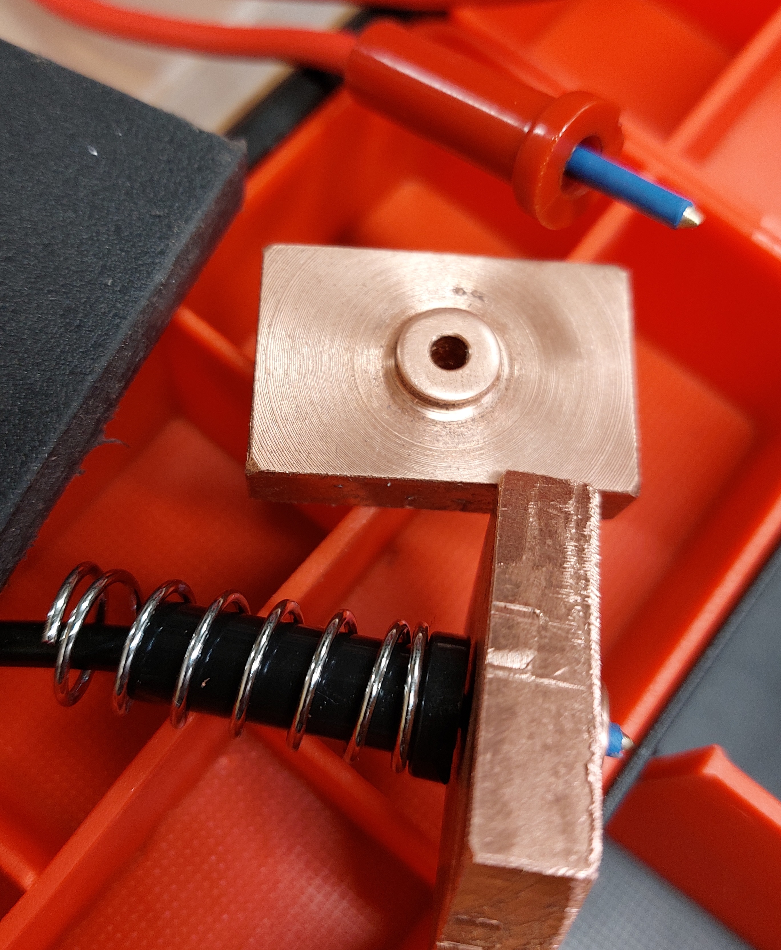
I have recently, with a friend, wanted to test the charge and discharge characteristics of lithium cells at very high currents. Up to 30 amps for ex-Tesla 21700s. I built a spring loaded tester to do this. I do love making experimental apparatus.
I DO NOT recommend you do this. Testing like this is extreme and can result in dangerous lithium fires, off gassing, burns etc. Again a blog of what I have done, not what you should do. The cell with damaged wrap is just for the photo and should not be used even this purpose. Oh, and there is some insulation missing on the copper contacts in this photo too. At one end of the cell, due to the whole ‘can’ being live, both positive and negative appear together separated by very little. The copper pad needs to be better protected against causing a short circuit. The shiny aluminium tube on the red centre wire could use some heatshrink too etc.
Experimental test jig with dangerous damaged cell. Unfinished copper pad insulation etc. etc.. Do not replicate.
The design of the tester is interesting in a few ways. First I made it from acrylic I bought as scrap from a local plastic supplier years ago. It is cool the way it shows the internal springs on the sense wires (more to come on that). To make it so transparent I fine sanded the acrylic and then waved a gas torch over the surface. I think it is called flame polishing. It is a stinky toxic process (again with the ‘this is not a how-to guide’ stuff) but I only did it to the tops of both end blocks.
The black plastic is an old chopping board, something with a higher melting temp would have been better. However it turns out that the moving copper pad (jaw?) does not get very hot compared to the other end due, I am pretty sure, to the design of the cell casing described above.
The brass rods (what I had) slide in and out of reamed holes on a bit of furniture wax. I need a variety of spring strengths for different purposes and they are easy to change on and off the rods too. RC car shock absorber springs were better than the heavy ones for the larger 21700 cells. Getting everything aligned was mostly done by stacking parts and drilling through on a accurately set up drill press. I have a milling machine but it was otherwise occupied and lacks a digital readout anyway.
So, sense wires. Each end is a Kelvin contact (as in the temperature scale that bears Lord Kelvin‘s name among other things) because it has two separate wires to the cell under test at each end (four wires total). Not the two heavy cables at each end (1.28mm^2 each), they work as one. The ‘two wires’ are the heavy cabling first and the finer central spring loaded wire second. With the two wires being separate, the huge currents that pass through the copper blocks, having come in on the fat wires, do not interact with the smaller sense leads.
This means the sense wires allow the voltage to be measured right at the cell on dedicated wires. The voltage drop that will appear on the far ends of the current wires will be massively higher than the voltage drop across the cell under test. This is due to resistance in the supply wires, the connection into the test device and contact resistance from the copper to the cell.
This picture show the display on the test equipment.
For the purposes of understanding the performance of the cell holder this device is reading voltage and current from the cell holder through an XT60 connector (amazing connectors). The voltage on the load wires is 2.299v. The actual voltage at the cell from the sense wires is 2.533 this means that resistance from the cell to the sensor in the test equipment is 0.234 at 24.06 amps(!!). This means the cell holder’s resistance, including an XT60 connector, is just under 10 milliohms. despite careful design, I did not expect such a good result. The tester right though to inside the test instrument is responsible for dissipating less than six watts.
Here are some parts fresh of the lathe.
The copper is off the lathe anyway, the probes are from an old school multi-meter, so old school it does not even use banana plugs there are the ends that plugged into the meter. Copper is the ideal material for electrical conductive. It is second in conductivity only to silver and (subject to surface oxidation) better than gold. As a metal for turning on the lathe it is a bit of a nightmare. It is so malleable that it wants to smear instead of cut. Sharp tungsten carbide tooling (designed for aluminum mostly but broadly ‘non-ferrous’) helped.
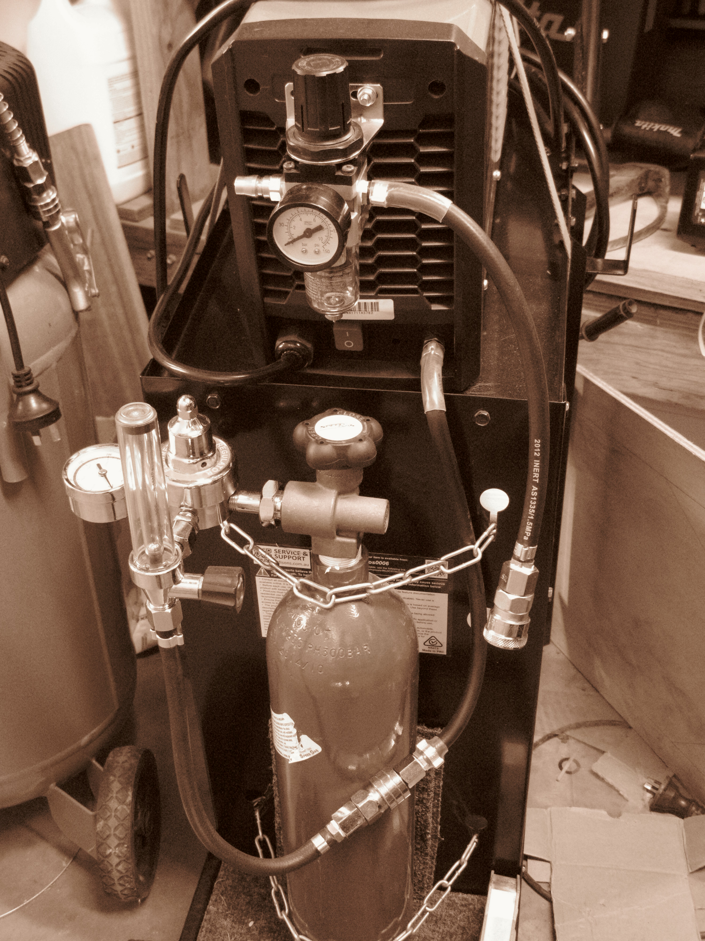
A while ago I bought a cheapish welder on eBay. Its a Rossi CT620iS. Its a multi function unit that does stick welding, DC TIG welding (no aluminum) and plasma cutting. The whole mess uses cheap standard parts that can be ordered freely on eBay from the usual places. The various torches have model numbers on them too.
Stick welding is straight forward. Buy a packet of sticks, hook up the ‘earth’ clamp, put a stick in the tongs and start covering everything in smoke, spatter and slag. Fun stuff.
TIG and plasma cutting require a bottle of Argon and compressed air respectively. The flow of gas is controlled in the welder by an electrically operated tap (solenoid valve). On this welder both gasses go into the same gas intake on the back bottom right. This does present some plumbing problems which I have solved like this:
This is a flammable gas free zone. I would absolutely not proceed like this with acetylene, propane, butane etc. However, I thought that for routing compressed air in through the regulator and moisture trap at the top (air goes in from my compressor at the left) compressed air fittings would suffice.
I also decided to use these fittings downstream from the Argon flow regulator that is screwed into the ‘swap and go’ Argon bottle. I have not found documentation to say this is ‘OK’ but I am happy with it unless someone tells me its dangerous somehow. I’d certainly not run bottle pressures through such fittings though.
As an aside, Argon is by far the most abundant gas in Earth’s atmosphere after Oxygen and Nitrogen. It is 20 times more abundant than Carbon dioxide which is the next most common gas. Oxygen, in second place, is 20 times more abundant than Argon.
As you can see, I am currently set up for Argon. The air regulator at the top is not connected at either the inlet or the outlet in the picture. To change I need to unplug the Argon and plug in the hose hanging down from the air regulator at the top. I then need to connect my air compressor at the top left.
I recently discovered the ‘ear clamps’ you can see on the hoses. These are excellent. I crimp them shut with some nail pulling pincers. There are of course proper tools… The clamps are single use but have no sharp bits sticking out of them and are, for want of a better term, ‘sprung shut’. If the hose under them compresses they can take up some of the space created. Screw clamps don’t seem to do this to nearly the same degree. I remove the ear clamps with a grinder by grinding at an ear until I am through.
There is also some glue lined heat shrink over some of the clamps. This is to provide strain relief and wear resistance. The outlet of the compressed air regulator at the top is an example.
A final word on Argon. It is a noble gas like Helium (and is therefore not chemically reactive) but much heavier. Being heavier I believe it is even more likely than helium to cause asphyxiation if inhaled because it settles in the bottom of the lungs. I am careful not breath Argon and I use it in a ventilated area.
As always, this is an account of what I did and not a ‘how to’ guide.
I am planning on buying a metal work lathe that has space in it for work pieces about 550mm in length. 550mm between centers. Optimum do a nice one that seems to fit bigger work than its specification indicates and which I can get locally, the Sieg SC4, which I am yet to see, also looks good. These lathes are a full step up in size from a minilathe but not industrial in any sense. They weigh around 100kg or more which is around double the weight of the best minilathes.
There are a couple of things about a lathe stand that might not be immediately obvious. First, a lathe should be running fairly smoothly a lot of the time. Unlike, a milling machine where cutter flutes engage and disengage, the lathe’s single point cutter is pushed into the work and stays there causing (I hope at least) relatively less vibration. I would not put a milling machine on a mobile tool trolley (again). Second, a lathe, with its length, relies heavily on the strength of its benchtop to avoid twisting. In fact leveling a lathe involves taking the twist out of it along its length and is an essential part of setup.
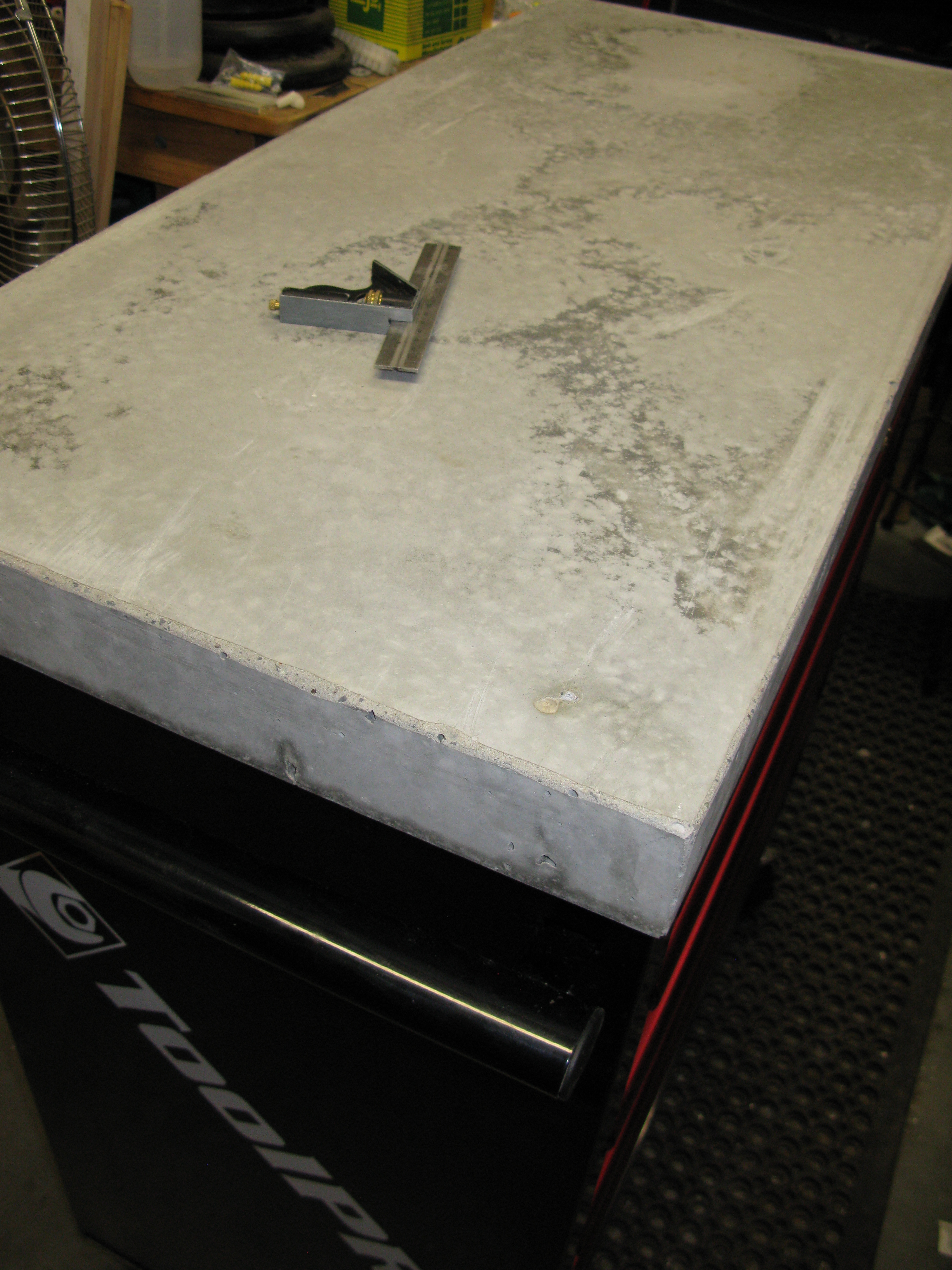
Like many home machinists I have limited space available and have decided to put my lathe on a rolling tool trolley draw cabinet thingy. However, they are a bit noisy if vibrated and the tops lack any real strength despite these trollies as a whole sometimes being rated for considerable weight loads. Most people solve this with thick wood tops it seems. However, they lack inertia and rigidity (being wood).
I decided to go with concrete. Here is the setup.
Melamine is great for casting concrete. Water resistant, slippery and smooth. The pine blocks have a slight angle on them so they contact at the top of the form-work first. I used 60kg of high strength mix, 10kg of cement powder 750ml of PVA concrete plasticiser and around 5l of water. It made for a thick but properly wet mix. I have a cheap ebay concrete vibrator (less than 100AUD delivered) that I used for settling the concrete, it has been awesome. To stop leaks I put a very thin bead of PVA glue around all the joins to seal the mould and it didn’t leak at all.
The piece of heavy duty particle board under the weights was already on top of my tool trolley, it fits into a rim on its top. As you can see I have created a good interface between my tool trolley timber top and the concrete (the particle board has stuck itself on actually). The side of the particle board facing the concrete was the old bench top-side and is painted, this should hold back some of the damp from the concrete. Once the mould is removed the concrete facing the melamine mould will be the new bench top. Clear as mud?
The 12mm rebar was in two pieces and is welded together. Rebar is not normally meant to be welded (too much carbon in it) but a rub with a file indicated it did not get super hard at least. Also, I don’t think I need the rebar parts to have any movement relative to each other on a work of this scale. Rebar is normally wired together. The rebar is diagonal because I thought it would resist twisting best this way.
As you can also see I used stainless screws in the 12mm rebar as stand offs. With the slab only being 60mm thick, precision was required. The screws were superglued in and superglued to the mould to hold the rebar in place. When it is all done I may be able to take out the screws or drill them out and fill the void, paint them or ignore them.
Lucky last, I have built this up on my deck because I know it is within a few mm of being a single plane across its whole surface.
One thing that does concern me a little is that the concrete and lathe ends up too heavy or too top heavy despite a very smooth and level workshop floor. I have made the concrete only a very little bit wider than the trolley with this in mind but it might not be stable enough. If I didn’t think it would be OK I would not have done it though only time will tell.
As always not a ‘how to’ guide, the way to safely set up a lathe is to the manufacturer’s spec. This is not such a setup, this is a record of what I did. Hope it was entertaining and thought provoking.
EDIT: Here is the finished bench top.
The rebar did move a little so that it is within 40mm of the edge of the slab at one point (instead of my target 50-55mm. The super glue to hold the standoffs to the formwork was not good enough. Top to bottom in the slab though remained spot on, the screw heads were at the surface. I actually unscrewed one of the screws! The other three broke off. I will fill the little craters with epoxy. For now I sealed them with super glue. I broke the edges with a flappy disc on an angle grinder. They work fine when the concrete is not completely hard (this was after five days).
I recently got a piece of scrap kitchen bench top and wondered how flat it was. I made a video that shows my setup to have a rough look. For my purposes it will do.
I have wanted digital readouts (DROs) on my mill for ages. It’s a bit hard to say what axis of a milling machine is most in need. The work being done is going to play a part in that decision. However on my mill the Z axis or up and down is a shocker. If you look at the first photo below showing the mill front on, the black hand-wheel on the left is the fine adjustment for height and used for milling operations. The scale is behind the wheel. The mark to read measurements off the scale/dial is on a small shiny plate you can see poking up at the right of the wheel. It’s all just about impossible to see.
As the photos show, I have hacked myself a DRO using a fairly long throw (25.4mm or 1 inch) digital dial indicator. Being digital, it has no dial so it’s really a ‘digital indicator’ (maybe a digimatic indicator.) ‘Digital dial indicator’, despite being an oxymoron, is unambiguous. Glad that’s clear now… Actual dial indicators are awesome, the slightest bump on the plunger causes the needle to spin wildly.
Digital dial indicators are cheap to buy on ebay or the other usual suspects (Ali Express etc.) at around $25 Australian and are decent quality. A review by AVE, complete with cussing and crudity and laughs, is available on YouTube – recommended viewing.
How does it work?
The top of the mill drops down towards the lower red section with the hand-wheel as the quill moves down (further obscuring the scale behind the wheel). This compresses the plunger on the dial indicator giving measurements down to 0.01mm.
Imagine that, I can drill a hole 17.01mm deep. Wow. I can also size parts by milling them with this same accuracy, also wow.
The full travel of the mill is 31mm, this is partly why the shiny aluminum part (milled to shape on the machine) is held on with magnets, if I forget it’s there it just slides out of the way. I hope the cast iron does not get too magnetised, but it’s out of the way and, lets be honest, this is a mill best used on softer metals anyway 🙂 Also, on the point of not being able to measure full travel in one stroke of the indicator, being a light mill it is best to not have the quill fully extended for precision work anyway to minimise flex. Finally, on this point, it is easy enough to move to say 20mm, slide the aluminum part down, reset the indicator to zero and start again from there. This is how I measured the full travel of the mill moments ago.
How did I make it?
The magnets are super-glued into flat bottomed holes that I made with a 10mm end mill (a ‘cutter’) that cuts in its centre (not all do). The magnets are ever so slightly recessed to protect them because they are quite brittle. I also used 12mm diameter end mill, for its length, to tidy up the roughly cut aluminium L shape. The side behind the length of the plunger in the photo was cut by the end of the cutter (which, on purpose, left the texture you can see). The dial indicator itself is attached to the mill with a screw that goes into a hole that I drilled with a battery drill and tapped. Swarf in the milling gearbox was not a problem because the gears were all about to be replaced (see my earlier post on rebuilding the gearbox) and I was cleaning everything.
Tangent: OK wordpress, it’s time we sorted out an Australian English spell checker. Hopefully there is a setting for it. Also, how could your dictionary not contain the word swarf? It is a favourite of mine and a handy way to describe the miscellaneous garbage produced by small children when they eat too (BTW).
What do I think about it?
The dial indicator DRO works well. It is easy to, using the fine feed, increase cut depth by .01mm increments. It is also so much neater and more accurate than hacks involving depth gauges based on digital vernier calipers. If I was starting again I would probably make it a little lighter. I did not know what size magnets I would use etc. but the extra weight is easily held by the three 10mm diameter magnets (they are strong ones) and it is solid.
My only complaint is that I could not use it while making the holes for the neodymium magnets…
UPDATE: I now lock the depth stop for the quill at around 22mm this makes sure I don’t bump the magnet block down and not notice. Honestly with a small mill the less quill extension the better anyway.
As always, a record of what I did. I am no engineer, this is not a ‘how to’ guide. Could this go wrong? Sure, if the aluminum thing falls off into a fly cutter it might take out an eye or send you reeling backwards onto your battle axe project.
The popular Sieg SX1 milling machine gearbox is made up of what seem to be glass fiber reinforced nylon gears. Tough for plastic, but not compared to steel. They are the white gears in the picture. As you can see I have missing teeth and, if you look closely at the gear on its edge, flattened off teeth. I nearly missed the flattened teeth when I first inspected the box and, as a result, nearly ordered less than a complete set of replacement plastic gears.
SX1 Micro Mill gears metal
Faced with the job of a complete rebuild I decided to replace the plastic gear-set with metal gears. 75AUD on Ali Express was what it took. It’s amazing that they are available so easily and, for what they are, cheaply, the magic of Chinese made tools.
Let’s be clear though, I did this to avoid the need for a further rebuild, not because I think I will be able to do bigger work with a mill of this size or because of upgrade-itis. In fact, the gear on the motor is made of softer plastic and, while the metal gear set included a metal version of it, I will not be using it. Its job, now that the rest of the box is metal, is to fail if I crash the mill (again). This was its job before too, it is listed as ‘sacrificial‘ in Arc’s parts list and I have a couple of spares. Sadly it did not save my original gear-set. Arc also have a guide to pulling apart and reassembling the mill (which I just found).
The replacement gears were very snug on the spindles and on their keys. The hi-low speed change gears (the two that move in the fork when the gear selector is turned) need to be able to move up and down. I honed the bore out with some wet and dry and cleaned up the key-way with a precision file (though just a little bit, the keyways in the gears have to be able to hold the key in place while they move up and down). Placing them on the spindle without the key and turning them by hand helped too, they key-way on the spindle is nice and sharp. These gears seemed to otherwise be of exactly the right profile. I was, of course, careful to make sure no abrasive particles or metal shavings made their way into the gearbox by carefully cleaning the parts as I went.
Fitting the key into these change gears was tricky, I ended up fitting the key and change gears to the spindle without the fork. That way I could tap the gears down onto the key, slide the key and two gears off as a single unit, fit them into the fork and put it all back together. I was very careful though, tapping onto the circlip that holds the top gear (the one that meshes with the motor drive) is not ideal. My copper faced hammer was just the tool for the job. I also used a shifting spanner on its side to give me a way to tap on both sides of a gear at once.
Removing the spindle gears required a gear puller, levering onto the casing with a screwdriver might get the first one off but will bend the casing. This is a drama because the casing locates the lid and the lid locates the motor and change gears relative to the spindle. I borrowed a puller from a neighbor but might get one like this from SuperCheap Auto (my local getting spot).
The other problem I had with the spindle gears was that they were, including the spacer, too thick. I cleaned up the faces of the gears with emery paper and sanded the spacer down a couple of mm. Also put a block of wood under the quill and tapped down on the gears using a piece of plastic conduit over the spindle. It’s still not quite enough, the circlip on the top of the spindle is engaged properly but pulled down a little at the middle, you may be able to see this in the photo.
This may be, in part, why the spindle and change gears are not all perfectly aligned top to bottom. I would worried about this except for the fact that the original plastic gears were also not perfectly aligned (worse I think, you can see it in the wear to the gear on its edge in the photo). Also, I am not worried about the metal ones wearing. One day I might have another look at this. Most likely it will involve milling a recess into the bottom of the bottom spindle gear. I will need to have a good look at whether it is already low enough though (maybe its time to get a borescope, not an endoscope they are for scoping one’s ‘end’ for medical reasons) and, if so, a couple more millimeters off the spacer should do it.
UPDATE: I used a friend’s lathe to turn down the spacer between the gears on the spindle to 12mm in height (or heighth for a disturbingly large number of North American machinists on YouTube). I then placed a spacer of approximately 1.3mm under the circlip and on top of the top gear on the spindle (I made it from a mudguard/fender washer using a step drill). This reduced the overall stack height by a couple of mm which means that the circlip now goes on properly and the gears align properly.
I used some nice grease with a little molybdenum disulfide in it to coat the gears, they are quite well made but not polished.
The mill works again, the tolerances are, like I say, not perfect but it seems fine. Hopefully I won’t crash it again. I was using a fly cutter (with a morse taper, not in a collet) and a tungsten carbide tipped cutter on steel. It actually worked quite well but wrecked it in the end. It may even be that the previous owner of the mill had compromised the gears before I got to them. There were signs he did not know what he was doing but there were also signs the mill was basically unused too. Whatever the reason, I won’t try it again.
As always, not a how to guide just showing what I did 🙂
I recently bought one of these players new on ebay. They are pretty heavily discounted at the moment despite being current according to Yamaha. The BD-S681, this player’s cheaper sibling, appears to be discontinued already based on a call to a local retailer despite both players being released mid 2016. This might explain the discount.
Why buy a high spec blu-ray player?
So why spend $550 on a shiny disc spinner? I have Netflix and Stan. There are a few reasons.
I have quite a few Bluray discs.
The Samsung player I had was pretty tacky
The Samsung player I had was crowded with ‘apps’ that didn’t interest me (I have a Chromecast).
I wanted a player for SACD, mostly for multi-channel music
I wanted a player for DVD-Audio (which I didn’t get see below)
So how does it work? The remote is nice to use, the player is fast, quiet, looks good and is nicely built. The menus are nice to look at and easy to use.
Unsurprisingly the BD-A1060 seems able to read a bunch of data off a Blu-ray disc and throw it out an HDMI cable at the highest of standards – much the same as my cheap Samsung player did.
Audio – mostly about surround music
I like surround sound music. Not as an effect added by a home cinema receiver/amplifier (though it can be cool I prefer stereo), but as a purposeful mix. I am not alone.
Pink Floyd apparently boycotted the release of Dark Side of the Moon because their four channel mix was not ready (which is AWESOME, thanks Alan Parsons). There is a Grammy category for surround music mixes too. I also like progressive rock and thanks to Steven Wilson there is plenty of surround content to listen to (Yes in particular for me).
The player can play SACDs beautifully (Brothers in Arms for example or an amazing Philip Glass harp performance). It also has a CD mode that slows the spindle motor down and disables ‘noisy’ video circuits etc. If the player is properly engineered (and I suspect it is) this should not create an audible difference. I can’t detect one but it’s pretty cool and shows the player was designed with more than video in mind. The ‘pure direct’ mode doesn’t make an audible difference for me either (on my receiver this is not true because of its bypassing of some DSP features) but it is a handy way to black out the TV.
One review says this player can do DVD-Audio playback in high resolution (rather than the DTS and prologic content that any DVD player can play). This is not what I found. It is possible it is firmware related. I updated mine when I first turned it on before I did any checks. Yamaha does not claim the player can do it.
However, it can play surround sound (six channel) 24bit 96khz .FLAC files over a network (DLNA) which mean I can easily rip the surround mixes and play them without navigating terrible DVD menus. Excellent. I can also play the DTS and Prologic mixes (which have lossy compression like, but different to, MP3) that are included on the DVD-Audio discs (as can any DVD player). For most purposes these DTS tracks are high resolution enough.
All the player’s multi channel audio is sent out over HDMI (HDMI 1.2, since 2005, has had this capability). My receiver does the digital to analogue conversion. The BD-A1060 only has two analogue audio outputs (left and right). The RCA sockets are solidly made and gold plated. Nice.
High resolution audio
It’s probably worth explaining that SACDs and DVD-Audio discs contain high resolution audio, usually 24bit 96khz, instead of the 16bit 44.1khz content of a CD. This only matters for very particular content. It has to be both beautifully recorded and very high in its dynamic range and even then it’s the 24bits that count the most. They give over 16 million volume increments (2^24) per sample instead of the over 60 thousand on a regular CD (2^16). Some recordings of the Tallis Scholars for example have very loud parts and very quiet parts. The quiet parts with ‘regular’ digital audio (16 bits) are encoded in relatively few bits at the bottom and can sound a little synthesized if paying attention.
But wait. There’s more. Many high resolution audio sources do not have the same mix or, more likely, mastering as the regular source. The audio engineers can assume a better standard of HiFi gear and set the tracks up accordingly. Greater dynamic range is an example of the differences that might be found. That is, the quietest and loudest sounds are further apart.
DACs
What about the analogue outputs on this up-spec player? I am yet to listen to them. I have a cold that has my ears ringing. However, audio DACs (digital to analogue converters) are no longer the state of the art technology they were. Once upon a time they were a big deal to engineer and implement but no longer. According to a post I found on the web this player uses the BurrBrown PCM1795. Unless Yamaha have horribly mis-implemented the DAC IC, despite the example circuit in the data sheet to get them started, the player will be good beyond human perception.
Other options?
If I cared more about 4k blu-ray discs and had deeper pockets the Oppo brand stuff would be the way to go. It would not match my Yamaha receiver the same though 🙂
SACD and DVD-Audio too much trouble?
DVD audio (for the DTS tracks) is easy enough. However, for high resolution surround sound, an ordinary blu-ray player has also recently become a good option. While SACD and DVD-A have required special support, the ‘Pure Audio‘ standard takes advantage of the already very high standard of audio (including lossless compression of high resolution audio) available on blu-ray disks. Much like an ordinary DVD player can do surround sound over DTS or prologic a modern Blu-ray player, including the BD-A1060 can use its ‘native’ formats. My hope is that this will make surround music more popular, there are quite a lot of Pure Audio releases already.
Conclusions
I am very happy with this player but, as always, if you want advice ask an expert. I am not one.


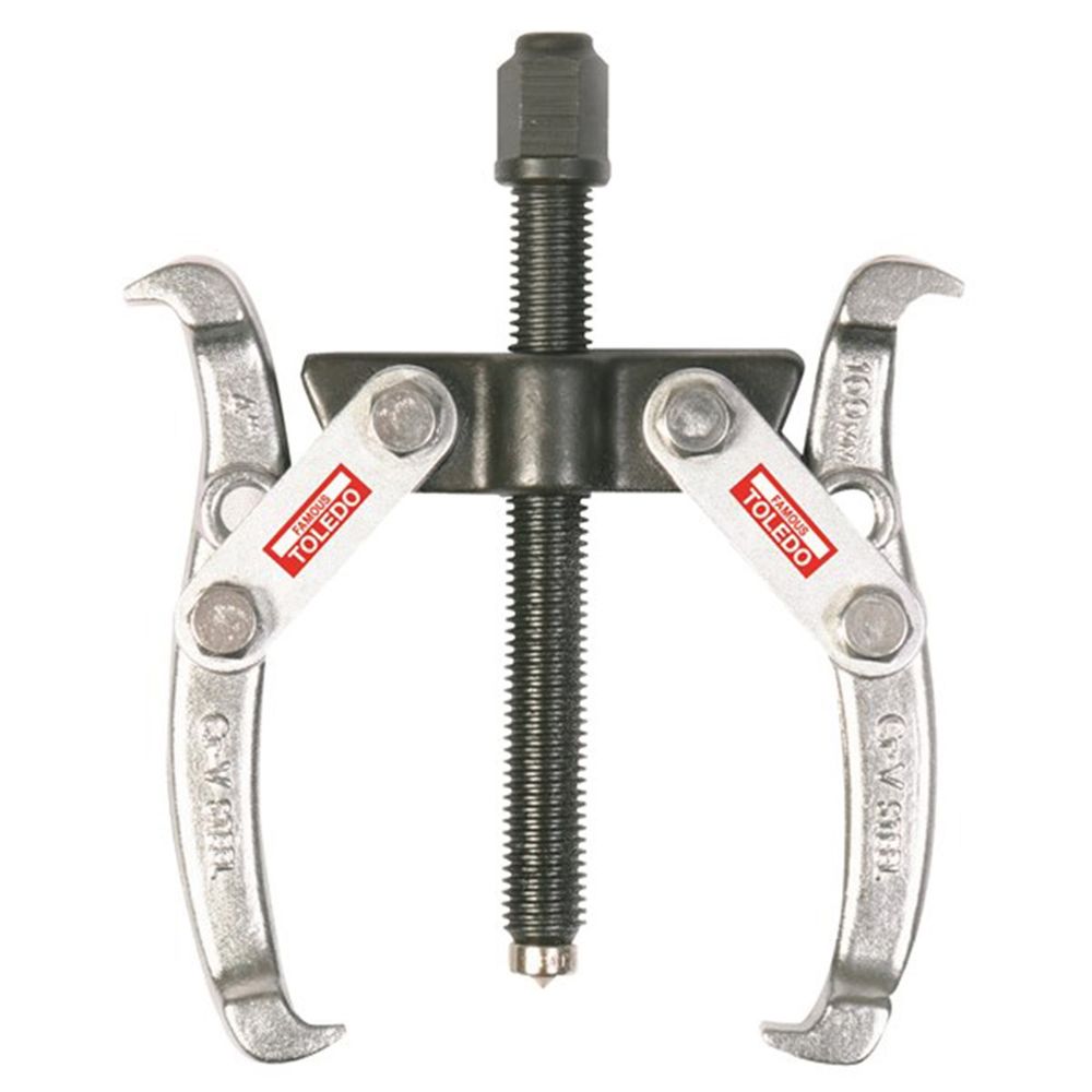 moving the spindle gears required a gear puller, levering onto the casing with a screwdriver might get the first one off but will bend the casing. This is a drama because the casing locates the lid and the lid locates the motor and change gears relative to the spindle. I borrowed a puller from a neighbor but might get one like this from SuperCheap Auto (my local getting spot).