
I now have a video up on YouTube showing some more details of this build.
Update April 23 2023: Picture of the display setup at the 2022 Canberra Vintage Computer Exhibition:

The Amiga 1000
The Commodore Amiga 1000, the first Amiga, launched on 23 July 1985. The launch spectacle showed off the new computer, and its state of the art technology, with live art by Andy Warhol amongst other things. The A1000 launch is on YouTube. The computer is a beautiful piece of industrial design and, at launch, was the best home computer available.

In early 1987 the Amiga 2000 was released. It was full of internal expansion ports and, soon after, new technologies for managing memory allocation (AGNUS chip) and a few extra screen modes that the A1000 could not support.
Phoenix Microtechnologies A1000 Enhanced Motherboard
In around 1991 an Australia business, Phoenix Microtechnologies Pty Ltd released the Phoenix replacement motherboard for the Amiga 1000. It supported the latest memory allocation technology (Amiga 3000 level) and had an A2000 expansion slot and an A2000 video card slot. It also had an onboard SCSI hard disk drive controller and maths co-processor if optioned. This is the motherboard pictured here.
The excellent web database of Amiga computer hardware ‘Big Book of Amiga Hardware’ contains a page on the Phoenix A1000 motherboard. It notes that the board’s creation was subscription funded. I cannot find a reference but there has been some talk that this is the first recorded crowd source funded IT project. Different information (though with much overlap) can be found on the also excellent Amiga Hardware Database. Amiga users are well served with hardware information.

This is an original board from the 90s (a few new-old-stock ones were released in the mid 2000s). The board is a beautiful thing including ICs with gold lids in ceramic packages (brown paper packages tied up in string etc.) It is covered in text, top and bottom. On the top these include creator Andrew J Wilson’s signature in the copper and the poem Desiderata in the silk screen. On the bottom the details include an apology ‘Sorry Sheldon we did it anyway’, thanks to 540 subscribers and a shout-out to the first subscriber and to ‘The Wizards of Amiga for a magic machine and O.S.’ Boxes for quality checks are near the front edge and are hand numbered and initialed.
I found an article in an old magazine of mine, the Australian Amiga Annual 1990. It is from the from the early days of the project and details the subscription / deposit funding model:

Having acquired a bare board many years ago I decided to make a working display case for it. Here is how it looks:


The picture shows a fast RAM expansion, SCSI2SD, floppy drive boot select switch, Kickstart switch with Kickstarts 1.3 and 3.1, drive light, hard disk auto configure enable switch. There are also connectors for an HDMI port (from a RGBtoHDMI yet to be installed in the video slot in this photo), a custom external PSU, and A2000 keyboard. The bumper stickers are to allow the machine to work upside down or on its side without anything getting scratched.
Here are some detail photos showing:
- power LED and HDD auto configure switch at the front
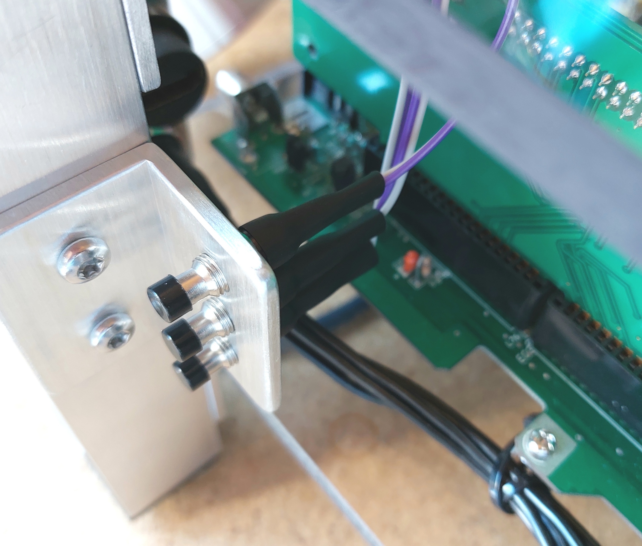
- joystick port strain relief at the front
- HDMI out and power in at the back
- keyboard adapter and drive/ Kickstart switches at the back.


The external power supply with its 3D printed badge looks great. Since the photograph was taken a thermostatically controlled 60mm fan has been added. While it is designed to be ultra safe there are no photos of the internals, this blog, as always, is not a ‘how to’ guide. There is certainly no ‘how to’ for DIY mains wiring anyway. That work is for licensed professionals.

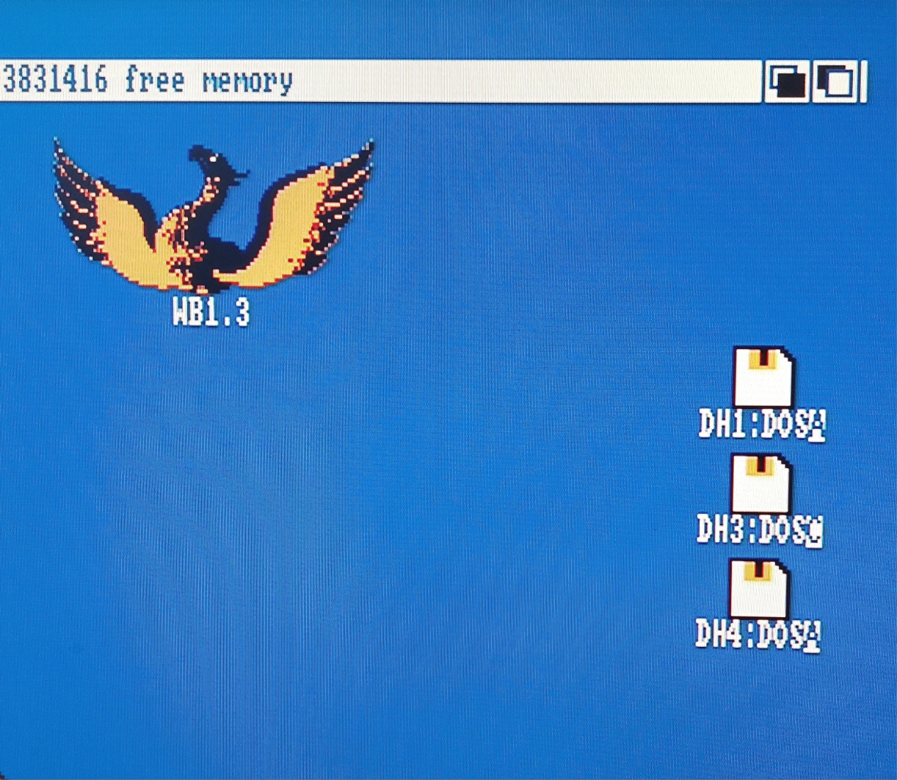
The computer works well and has been running Workbench 1.3 and 3.1 for days now. WHDLoad is supported and all Amiga Test Kit tests pass. It is an excellent Amiga.
April update: Thanks to intric8 at Amiga Love, I now have a really nice phoenix sticker on the case:

I was very pleased to add this, I did not have the logo anywhere on the computer until this arrived from the other side of the planet.
Build details: Electronics and switches
Power LED: The two colour power LED was, to my surprise, incredibly tricky. I wanted to implement the colours specified in the manual. This involves an orange ‘on’ colour turning to green during HDD activity, red is used to denote a system malfunction of some kind. I purchased a large (10mm 3/8″) two colour LED, it has three legs. The middle leg is common or negative and the remaining two legs power red or green. So, when the computer is simply on both red and green LEDs are on making orange. When the hard drive is active the red LED turns off.
The manual gives no explanation of exactly how the factory power LED is wired up (it replaced the Commodore LED). It does mention a ‘hidden resistor.’ LEDs connected to power need a resistor in series to keep them from burning out and one at least was, apparently, needed in the cabling. Various attempts, including a resistor on common and two resistors, one on each colour, failed to work properly.
It became clear that the green LED needed a resistor (on the green positive lead at 100ohms for my LED) but the red LED needed a direct connection to the motherboard. Something about the switching circuit, perhaps just an onboard resistor to guarantee low current switching, meant that any further resistance on red stopped it from working. So the ‘hidden resistor’ is for the green LED only.
The manual is also not perfectly clear on which KED pin is what. I have connected LED2 REAR to red, LED1 RIGHT to green (through a 100ohm resistor) and LED1 LEFT to the LED’s negative lead. The RIGHT, LEFT, REAR, FRONT nomenclature is from the phoenix manual. Looking at the board from above so that the ports are at the REAR the other directions were correct.
Kickstart Switch: Like the power LED I think this was supposed to be purchased from Phoenix Microtechnologies. The manual provides excellent information on how to jumper the Kickstart selection link block. The factory switch has three leads.
I have two genuine ROMs (not EPROMS) as U53-ROM1 (KS3.1) and U54-ROM2 (KS 1.3). The manual is clear that I need to leave the FRONT two pins of L42 open and switch the rear two. This is what I did and it works well. The third wire on the factory switch should go from L42 REAR RIGHT to L35 middle. This will prevent the HDD from trying to auto boot off the second ROM. This makes sense in most original cases because the Workbench install will only match one ROM. Interestingly this is not a proper implementation of L35 it should be either centre and LEFT or (XOR) centre and RIGHT.

Please note, I have not actually built one of these. This is a blog about what I have done, not advice on what you should do without having a good hard look at this for yourself 🙂
Hard Drive Auto Configure Switch: I have wired a switch up (next to the power light) to separately operate L35 rather than use the factory layout tied to a Kickstart switch. This lets me switch hard drives (MicroSD cards) and boot different installations under different Kickstarts. It’s also the only way to see the glorious insert workbench icons splash screens 🙂
The switch is also necessary with my setup to allow booting from floppy with an un-configured hard disk drive (blank MicroSD card in my SCSItoSD). For some reason the computer gets hung up on the un-partitioned card. It would then not see partitioned but un-formatted space after booting with a floppy until the switch was back in the auto configure position. The less said about how long it took to figure this out the better.
Contrary to my reading of the manual I needed to leave L14 open.
Floppy Drive Swap Switch: The floppy swap switch allows an external drive to function as DF0: for booting. I need this because, to keep the board clear for display, I have not attached a ribbon cable to the floppy header. Floppy numbering (allowing a user to hack into the CIA lines out to the floppy connectors) is done at L8. Four jumpers each running FRONT to REAR (or REAR to FRONT, same same) is the default setting (check the manual for yourself!) but if the leftmost two are cross connected in an X DF0: is on the outside and DF1 can be on the inside. The manual contains further details.
I had to draw a diagram to figure out the switch (though you will see a white dupont connector cable loop in the first picture of the board in this post that sufficed before I made the switch.) Figuring out an order of operations to get the heatshrink perfect was also tricky.

The switch drawing above is rough but effective. The two boxes drawn over the switch contacts (top) give a guide about what is grouped together in each of the two switch states. With hindsight, a centre off switch might be a useful way to disarm all drives (I think that is what it would do), especially with an external gotek/flashfloppy emulator which usually has a disk ‘inserted’ at all times.
Power supply: The supply is connected/strain relieved with a 7 pin GX20 aviation plug, power then goes to the motherboard connector. The Phoenix board has a jumper like the A2000 so that a tick is not strictly necessary (L125 RIGHT to obtain tick onboard). However, a crystal locked tick PCB is readily available and is incredibly precise. I have a spare PCB if you need one.
I checked the motherboard connector pinout against a real A1000 PSU about five times after being sure I built it right in the first place. Once check involved drawing the 7 pin motherboard connector twice, I then filled in the voltages for one supply and hid that drawing, I then did the same for the other supply and compared the two drawings.
RGB2HDMI: The Amiga’s video out is a dated standard. It is an analogue video connector on a DB23 plug. It does work well and there are plenty of options for converting these signals into whatever format is required.
Fairly recently though work was done to intercept the digital signals and use a Raspberry Pi Zero to convert them directly to HDMI. For computers without internal slots, like the Amiga 500 or the original Amiga 1000, the RGB2HDMI is plugged in under a chip (as are things like the Indivision converters which work OK). Starting with the Amiga 2000, a video slot with all the digital signals exposed became available. The Phoenix board also has such a slot, here is picture showing the RGB2HDMI card, the button bracket and, blurry in black at the back, the HDMI socket that will provide full strain relief when I can finally purchase a Pi Zero. Once I know the card works I will move the button connectors to the side of the card closest to the switches (I would not attempt to do a warranty return on a card I had soldered on).
Helpfully pin 1 on the slot is marked by a diagonal in the corner of its box on the silkscreen of the PCB and pin two is clearly marked on the RGB2HDMI. I also have not come across any information that the video slot is back to front and the RGB2HDMI has an arrow on it that has to point to the back of the computer. I have some recollection that the Phoenix board’s Zorro slot is back to front (it is on the ‘wrong’ side of the CPU compared to the A500 and A2000) but I am not sure, investigations are required.
The button bracket is drilled and tapped for the buttons. These switches, like many similar items including some rotary encoders I have, use an odd thread: “M7 fine”. It is a metric 7mm thread and with closely spaced threads of 0.75mm pitch (the distance between thread peaks). Most metric thread charts have no M7 thread at all and M6 normally has a 1.0mm pitch. I bought a tap especially. The drill size is odd too at 6.25mm (thread size – thread pitch for metric). Thankfully 6.2mm drills are fairly easy to find and in soft materials have been close enough.
Clock Battery: A standard CR2032 clock battery holder fitted well with only an extremely minor zigzag in one of its pins. I took care to run the zigzag close to the holder and to not mess up the clip mechanism which assumed the pins will be pushed fully down through the PCB. It just cleared the poetry to the LEFT of the battery position. I considered using a smaller CR1220, my A1200 clock uses one, but given the amount of time these computers are left disconnected from the mains and running on the backup battery I concluded that the larger cell was a good idea.
I do need to check whether the board is trying to charge this cell. A rechargeable cell in the 2032 form factor may be required.


The second photo shows that the hole in the motherboard is barely impinged upon too. If it mattered I would whittle down the plastic of the cell holder ever so slightly for perfect clearance.
Capacitors: As far as I can tell all the yellow capacitors on the board are plastic film capacitors. They have no electrolyte in them to leak and, subject to high voltage transients (unlikely) should last (for practical purposes) forever. Of the five electrolytics two are near the audio ports, I left them alone. The three near the power connector see significant ripple currents and were discoloured on top and there were rings that looked liked dried liquid on the PCB underneath the 12v and 5v capacitors them when I removed them. They were made by Daewoo. I took a picture of the board with the capacitors removed, an old capacitor is in the picture leaning on the power connector:

I replaced them with the best parts I could buy. Long life, 125C low ESR Vishay capacitors. Like the originals they are 470uF 16V capacitors. They are 1.5x the height (height-th if using inches) of the originals but the same diameter. The -5v capacitor had not leaked (it does not see much ripple current). This is partly why I do not suspect trouble with the audio capacitors (I also have a proper LCR meter which suggested the removed capacitors were still pretty OK for capacitance and ESR). On the topic of the -5v capacitor (which is in a sense back to front) the silk screen was right on my board. I always photograph capacitors prior to removal for checking against the silkscreen when the paranoia arrives at soldering time (cidering time if soldering in inches).

New capacitors installed. Next to AGNUS, behind the leftmost capacitor, the hole in the motherboard is plugged with black plastic. This is a part I turned to be a gentle push fit into the board. It goes in from the bottom and stops on a 1mm shoulder. Underneath there is a 15mm long cylinder (same length as the PCB standoffs) to support the board in the middle.
Materials: DPDT switches, wires and headers from long since discarded PC case plus some extra dupont headers. 5 pin IEC socket (keyboard) 4P4C plug (keyboard, these are quite skinny, they have 4 positions and all four are connected, phone plugs usually have 8 positions of which only four are used/connected), 7 pin GX20 aviation plug (power), HDMI pass-through plug, 10mm Red/Green LED and 100 ohm resistor.
Build details: Aluminium and clear polycarbonate
The top and bottom are 8mm thick sheets of machine guard poly-carbonate from Bunnings (I think in the US it would be Home Depot). Machine guard plastics should be static dissipative (to prevent dust from machines being attracted to them.) It appears to be. It is stronger and harder than acrylic and provides a good basal platen for the motherboard, in my design it is structural too and while there is a little wobble without the top on, it is rock solid once it is screwed on.
The motherboard mounting holes were tricky. They had to be close to spot on. I had originally planned to tap the poly-carbonate but there would have been no tolerance other than the diameter of the holes in the board. By using screws and threaded standoffs I could drill the holes in the poly-carbonate 0.5mm over-size too. Initial positioning of the board was done with three holes, in each hole I had a pin (turned to size on my lathe) that exactly matched the motherboard holes and the hole in the poly-carbonate. This super accurate positioning (the board could hardly move at all and its holes were perfectly concentric with my first three holes) meant I could then take a drill, close to the size of the motherboard holes, and spin it by hand to mark the locations in the plastic. The final 15mm standoff height was chosen to enable the ram expansion to fit on the side expansion connector.
I was not sure how to get a nice brushed aluminium look. The parts all needed tidying up, thankfully someone on YouTube had a clue and I used their method. The picture below shows one of the legs. It is marked to show where it goes (the parts are interchangeable but do work best where they were made. The dot on the right hand side is superglue from assembly prior to drilling and tapping the leg.
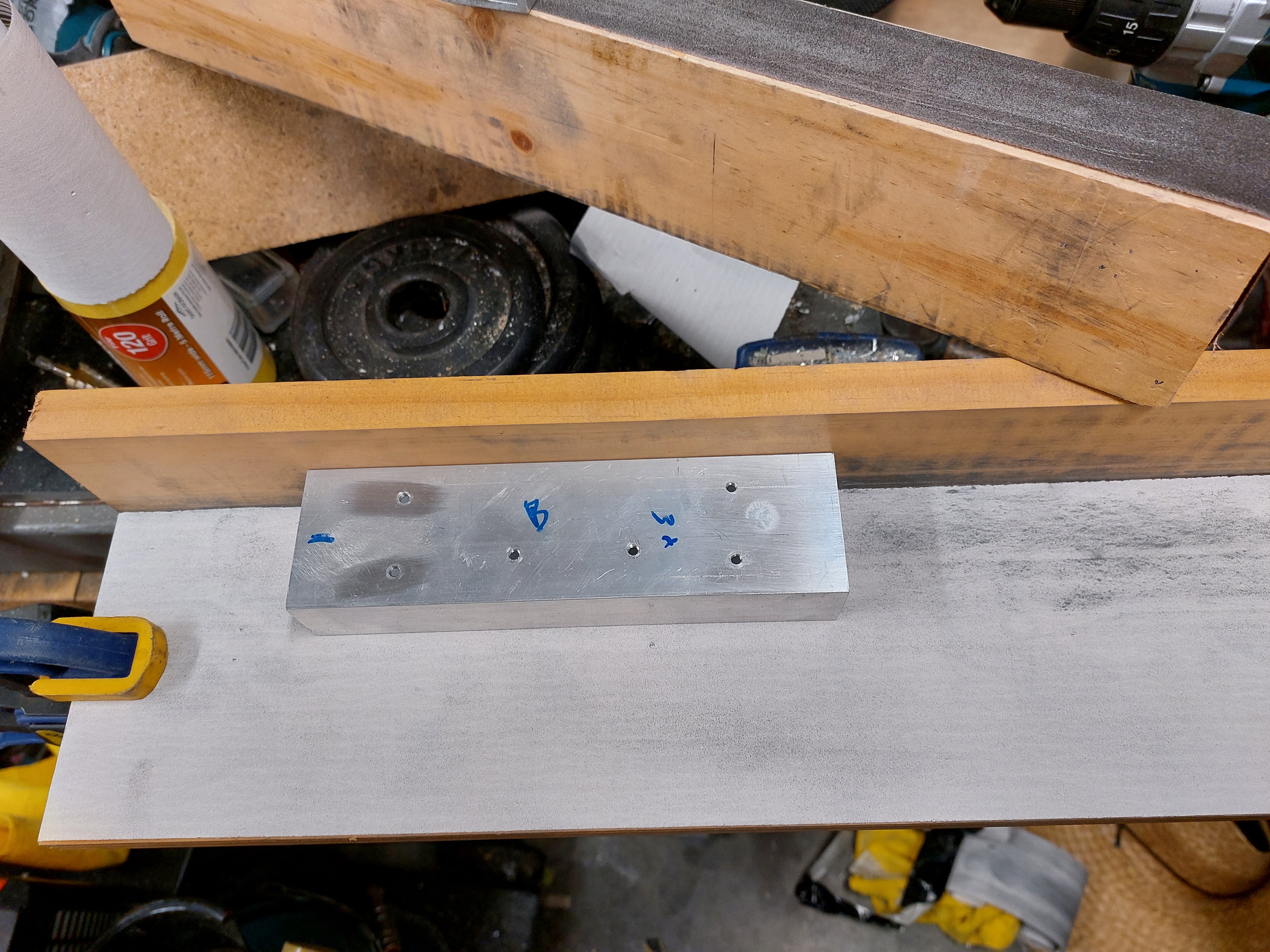
There is not a lot to say about the aluminium. The parts are stamped to show which one goes where but they are close to perfectly interchangeable. It is laborious but the method to attach a piece of angle to a rectangular leg was:
- Drill holes in angle to tap drill size
- Clamp or superglue (you can see some glue in the picture above) the angle into place. Spacer blocks are always more accurate than measurement for this purpose.
- Drill through the tap hole in the angle into the leg.
- Tap the leg
- Drill a clearance hole in the angle. This can be slightly oversize if some tolerance is required.
Materials: Aluminium section and end plugs, aluminium angle, lots of stainless screws and washers, 15mm PCB standoffs, 8mm poly-carbonate machine guard plastic (should be static dissipative).
Build details: Jumpers, SCSItoSD, pbscsi.device and Worbench Installs
Jumpers, jumper blocks, links: The Phoenix manual talks about links, not jumper pins or jumper blocks. In any case things can be configured by joining up a bunch sticky outy bits of conductive metal on the board. Most older motherboards have at least some jumper pins on them. The Phoenix board is a porcupine.
I have mentioned jumpers a few times in this blog post. The two reference documents I turned to for the Phoenix board were the original manual (the drawing showing locations of jumpers was a life saver, I printed and laminated it) and a PDF that is useful to clear things up available from Retrohax article. I note again that with my current setup I need to leave L14 open despite the manual’s default settings recommendation.
I use jumpers with tabs on the top for easy removal and installation, they also show where I have been fiddling because default ones are usually standard stubby ones. Recommended.

A final observation on jumpers on a board of this age. If the expected result is not achieved it could be a worn out jumper. My board was set to use an onboard source for tick when I got it. A factory power supply had worked days before, mine without tick did not. I pulled off the jumper, was pleased to note a loose fit on the suspect part, and put on one of my own. Problem solved.
SCSItoSD: Instead of a precision spinnage of magnetic media that is a vintage hard disk drive, the SCSI controller/interface on the Phoenix board is connected to a hard disk drive emulator, the SCSItoSD v5. There are newer and better emulators including the Zulu SCSI which is top shelf stuff. I bought this one years ago though, when the future of vintage computing was unclear and I did wonder if it was my only chance to get a drive emulator. I am glad to have it in use.
The drive emulator is configurable over USB using a small executable file under Windows. Mine is set to defaults (largely), to emulate two 2gigabyte SCSI2 hard drives at Device 0 and Device 1. One gigabyte would probably have been better, given where I ended up, but it is set up now and working well (EDIT: but temptation got me and I created another train wreck, now emulating 952 megabytes, 900 more than I had in the 90s). With my MAST ram expansion, earlier versions of which are said to interfere with hard drive autobooting in the Phoenix manual, I had to set a 2 second delay into the drive emulator (one second was slightly marginal). If it was set to be ready as soon as it could be the computer would only autoboot after a soft (keyboard) reset when first turned on.
It was not clear what would happen if I removed the microSD card from the drive emulator, connected it to a Windows computer and mounted the card as a hard drive in the WinUAE Amiga emulator. To my delight it immediately booted my Phoenix install on Device0 and allowed me to copy files to both of the partitions on it. Device1 did not auto-configure (fair enough) and I have not yet tried to access it under WinUAE.
I deleted a chunk of stuff here on 26 April 2023. I had hard drive problems using default settings (the ROM vJ with no polled SCSI software update at boot, and link 30 open). I found I could reliably bring the problem on by ‘leaving out’ and then ‘putting away’ the DOpus icon.
At 25cm my SCSI cable was not a particularly long cable. However, with thanks to information from the friendly people on the A1K forums, I was moved to shorten it to 8cm. The problems is not completely fixed but is much better. If I load the polled SCSI driver it works fine, just a bit slower. I may be able to clean up the remaining problems with SCSI2SD settings.
I am just going to run this with the Phoenix HDD defaults. Using the sysinfo HDD speed test the default settings give me 112500 bytes/second where under polled SCSI with or without L30 closed I was in the 60000 range. I won’t be installing a CD ROM so polled SCSI does not matter much. I won’t be doing the hardware mode either, it sounds great but I am trying to leave this one original.
pbSCSI.device: The Amiga’s operating system is beautiful. It is parsimonious and highly configurable. It is reason enough to spend time on one of these early computers, just to see how clever an OS can be. Transitioning from AmigaDOS to Windows 3.1.1 was grim (however necessary it was at the time). It was not until Windows 2000 that I felt I was back on a winner and I embraced it with enthusiasm, but still missed my AmigaDOS shell.
pbSCSI.device is the device file for the Phoenix board SCSI controller. It goes in the devices (DEVS) draw, it is a tool type for the hard disk configuration tool icon (or argument at the command line) and it is on the ROM on the Phoenix board. For ease of use I keep pbSCSI.device in DEVS on my installs but don’t use it much after first setup is done. I have amended reference to SCSI.device in HDTooBox’s tool types to refer to pbSCSI.device (I just right clicked on the icon and typed in the “pb”.)

The picture shows the mouse pointer hovering over the icons/information menu. When the HDToolBox is the selected icon, clicking here brings up the window for the icon shown. The line in the Tool Types: SCSI_DEVICE_NAME=pbSCSI.device did not previously say ‘pb’ before ‘SCSI’. I had previously copied pbscsi.device from the phoenix floppy to my Install3.1 floppy disk’s DEVS drawer. I found I also needed to copy FastFileSystem from the install floppy to L: on WB3.1.
The FFS on the 1.3 install, I believe, is a specific version that goes with it (it is about half the size and I am left wondering if the 3.1 version contains two versions in one file). One day I will try replacing it with the 3.1 version to see what happens.
When I am feeling brave I am going to start using Polled pbSCSI.device for a bit of a speed increase. Such a flexible OS. I will not be amending the board for a pseudo DMA configuration.
Install Workbench 3.1 to Hard Drive: With the board powered up, connected to a display, keyboard, mouse and floppy drive emulator as device DF0: it was time to install Workbench. This is how I install Workbench 3.1, it should be the same for 1.3:
- Turn off hard drive auto configure at link 35 (to allow floppy boot with unconfigured SD card in my drive emulator).
- Boot from install3.1 with pbscsi.device in the tool type for the HDToolbox icon after putting pbscsi.device into DEVS.
I do all partitioning and formatting from there. This is the only way I can know that all drives have the 3.1 version of Fast File System. - Delete any old drive types and autodetect the SCSItoSD drive (HDToolBox).
- Partition the drive. A few hundred megabytes for Workbench is enormous. I am not sure exactly where the limits are, but I am emulating a 952 megabyte drive. While I was still learning, the HDToolBox on the Phoenix floppy at least did not work at all with more than 2gig and seemed less than perfectly reliable over 1gig. More experimentation would help (HDToolBox).
- Save changes to drive and low level format and save changes to drive again for good measure (HDToolBox).
- Turn on hard drive auto configure at link 35. Boot the Workbench Install floppy again. Turning auto configure on makes the hard drive partitions pop up (as I should have always expected but these things are a variable (sic) soup).
- Format the drives using Workbench’s format menu. I have international and cache turned off. I have not tested with it turned on. Then double click on install Workbench.
Here is an install (one of many along the way):

I grabbed disk.info from the phoenix floppy and put it on DH0: where my Workbench install lives to get the Phoenix icon on it. Not a bad image. My old HP wide gamut monitor has an s-video input and I have an Amiga RGB to s-video adapter from Kipper2k. It is perfect for testing because it is utterly reliable, no wondering what has caused a black screen.
Workbench 1.3.3 Install: It has to be, I think, at the start of device 0. It is essentially the same as a WB3.1 install I think. There is no install file for WB 1.3, just copy over WB1.3 and Extras to the drive. Something like “Copy DF0: to DH0: ALL”. The all argument takes the contents of folders rather than just creating empty folders.
I copied the contexts of the Phoenix disk over first for some vintage goodness. There is some good stuff on that disk including the document viewer c/phoenixview. I also spooled on ARP, the Amiga resource project floppy. It adds a bunch of stuff that Commodore added as standard in later revision of Workbench.
One of my Workbench 1.3 installs I made using install scripts mentioned in the Phoenix manual that were on a floppy I am yet to find online (and may need to upload). It was magical. The floppy says it is from 21 October 1991 during boot. The first thing it does is copy over (I think) the entirety of the Phoenix disk before copying over Workbench. There are some nice things on their that lend authenticity to a Phoenix board build.

Workbench 1.3.3 is stable but it is there for historical purposes and for niche software. By the time Phoenix was a thing Kickstart 2.04 was around and the improvement in user experience (I recall the joy of upgrading my Amiga 2000 at the time) is incredible. Workbench 3 looks very similar to 2 but supports more modern software. The only thing I miss about 2 is the even blue dot workbench background texture, the one in 3 is not as nice. I will try and copy it over.
Auto selection of Workbench install based on Kickstart selected: It would be nice, I thought, to boot the right version of Workbench depending on the Kickstart (1.3 or 3.1) selected at boot. It is possible, but I have learned that with a SCSItoSD at least it cannot be done reliably. Read more under the heading about SCSItoSD.
File systems are important here. It is easy to end up with multiple versions of Fast File System across multiple drives. I believe this was a source of unreliability for me. It also seems reasonable to conclude that booting into 1.3 with one version of FFS and then throwing over to 3.1 which is setup with a different FFS is a bad idea.
My solution was to add the pbscsi.device tooltype on my WB3.1 HDToolBox (as mentioned above) and create FFS partitions for all drives there. I also formatted them all in Workbench 3.1 in FFS (no directory cache, no international mode which I think is what 1.3 requires but not sure).
Booting Workbench 1.3 off a partition formatted in 3.1’s (sic) FFS means there are some aberrant additional drive icons on the desktop. I don’t think there is anything to do but hide them under icons for other things. I have also noted that the second SCSI device, while formatted the same, does not produce one of the aberrant icons. Here they are in a photo:
I have grown to be glad to seem them over multiple install iterations. It means I have things right.
So on to the dual boot setup. It has to be so that the computer starts by trying to boot 1.3. A 1.3 ROM cannot ‘see’ a 3.1 partition to kick off the process. This means that in every case the computer will start by heading off into the s/startup-sequence script in the Workbench 1.3.3 install. This guide explains how to automatically detect which Kickstart ROM is operational and to boot the proper Workbench version accordingly.
In summary the original 1.3 startup-sequence gets renamed. A new startup-sequence is created that checks the Kickstart version and uses an if statement to either use the original but renamed startup-sequence or do some preparatory work and run the 3.1 installation’s startup-sequence.
The guide is good (though commentary on FFS versions would have helped me) but it can be improved. I added some echo statements, alongside the assigns specified in the guide to tell the user what is going on:
Echo ” “
Echo “Kickstart newer than 1.3 detected”
Echo “BOOTING Workbench 3.1 install on DH1:”
The first echo is for a blank line and, yes, I fixed the ‘Workbenmch’ typo, the version in the photo was an attempt to fix ‘Workbemch’:

The second problem is that I think the 1.3 startup-sequence is still running while Workbench 3.1 is initializing. I think AmigaDOS (and probably every other OS) holds a script open until it finishes. So, until the 3.1 startup-sequence has done ‘loadwb’ and ‘endcli’ the custom startup-sequence on the 1.3 partition is still open. It will not close until after 3.1’s sequence says endcli at which point control returns to the 1.3 startup-sequence and it can do an endcli.
This causes a requester to pop up multiple times complaining that “Intuition is attempting to reset the workbench screen.” I added the DELAY argument to LoadWB at the end of the Workbench 3.1 startup-sequence so “LoadWB DELAY“. This means that the intuition requester is seen only once and cancels itself. I also have to always remember the way to edit documents on an Amiga is Ed not Edit. Typing ‘q’ and enter exits edit when accidentally launched, the escape key, x then enter saves and exits ed.
In the hope of snapping the 1.3 startup sequence shut fast at the end of a 3.1 boot I also changed the code used in the guide script. I think the original code is more ‘by the book’ but my main programing experience is BASIC on a Commodore 64 so don’t stand too close when I am working 😉 I also added a >NIL: to the first line to prevent it reporting the version on screen. Here it is in phoenixview:

Dual or multi-boot can also be done with nice packages on Aminet (Aminet remains a phenomenal resource and an example of just how wonderful Amiga still is in 2023), as can advanced high speed assign management.
In some ways dual boot is a fall back position. For a squeaky clean boot, holding down two mouse buttons and booting from DH1: right at the start is best. To do this there is another variation on the guide I linked to. DH1 has to be bootable too, it just has to have a lower boot priority number than DH0: (containing Workbench 1.3). I have DH0: as 1 and DH1: as 0 (sic). Boot priorities are set in the hard drive partitioning menus of Tools/HDToolBox. Always have to remember to press return after typing numbers into the boxes to lock them in, classic Amiga.
I hope my experience are interesting and perhaps useful for someone else. Like I say though, this blog is a record of what I did. Not advice on what you should do.

Hi, Great article. I’ve just downloaded it to print and read, as I’ve recently dug out a Phoenix board I purchased second hand yeas ago, and never got around to working on. It was missing all the Phoenix Tech supplied kickstart and drive switches etc, so your write up will certainly assist. My first step though is to get it to give me some signs of life, as it’s currently just powering up to a black screen! Cheers, Artie
LikeLiked by 1 person
Thanks, please check back now and again. I am still learning a few bits and pieces and will post them here. If SCSI boot is enabled and there is no drive you might find you have a black screen for quite a while under 3.1 before anything happens. KS1.3 is easier, it goes quite white quite fast. I found the default jumper settings listed in the manual were a good place to start.
LikeLike
Hi Arthur, I think I am done updating this now. Added a bunch of stuff on getting SCSI working reliably with SCSItoSD. I thought I was done some time ago but… 🙂
LikeLike